Sharp X-70H Wartungshandbuch
Stöbern Sie online oder laden Sie Wartungshandbuch nach CD Spieler Sharp X-70H herunter. Sharp X-70H Service manual Benutzerhandbuch
- Seite / 64
- Inhaltsverzeichnis
- LESEZEICHEN
- SERVICE MANUAL 1
- SPECIFICATIONS 3
- NAMES OF PARTS 4
- ■ Speaker section 5
- RESETTING THE MICROCOMPUTER 6
- DISASSEMBLY 8
- XL-60H/70H 10
- TAPE MECHANISM SECTION 10
- CD MECHANISM SECTION 11
- ADJUSTMENT 12
- TEST MODE 14
- ERROR LIST 20
- 1 2 3 21
- MAIN PWB-A1 32
- DISPLAY PWB-A2 33
- LED PWB-A4 33
- POWER PWB-B1 35
- POWER AMP 35
- WAVEFORMS OF CD CIRCUIT 36
- When the CD does not function 37
- • Laser failure 39
- • Focus failure 39
- 1.5~2.5sec 40
- • HF error 41
- • No sound 41
- • Sled servo failure 42
- • Track search failure 42
- FUNCTION TABLE OF IC 43
- Figure 44 BLOCK DIAGRAM OF IC 44
- Figure 46 BLOCK DIAGRAM OF IC 46
- Figure 47 BLOCK DIAGRAM OF IC 47
- Figure 50 BLOCK DIAGRAM OF IC 50
- Figure 51 BLOCK DIAGRAM OF IC 51
- Figure 52 LCD SEGMENT 52
- PARTS GUIDE 53
- CP-XL60H 62
- CP-XL70H 63
Inhaltsverzeichnis
– 1 –XL-60H/70H CONTENTSPageSAFETY PRECAUTION FOR SERVICE MANUAL ...
XL-60H/70H– 10 –TAPE MECHANISM SECTIONPerform steps 1 to 8 and 10 of the disassembly method toremove the tape mechanism. (See page 8.)How to remove th
– 11 –XL-60H/70HFigure 11-4How to remove the pickup (See Fig. 11-4)1. Remove the mechanism cover, paying attention to thepawls (A1) x 4 pcs.2. Remove
XL-60H/70H– 12 –MECHANISM SECTION• Driving Force CheckTorque MeterSpecified ValuePlay: TW-2412 Over 80 g• Torque CheckTorque MeterPlay: TW-2111 30 to
– 13 –XL-60H/70H34271561110141512131698VddaVssaMPXINTESTTESTCLK(4.332MHz)OSCXINXOUTRDS-ID/READYRSTMODERDCLRDDAVssdVdddPLL(57kHz)CLOCKRECOVERY(1187.5Hz
XL-60H/70H– 14 –2. CD Test Mode (TEST 1)In the CD test mode the operation of each step is enabled even when the LID-SW is off. However, if focus canno
– 15 –XL-60H/70HThe time display indicates always "0:00".When the following buttons are pressed in this state, the operation is executed as
XL-60H/70H– 16 –3. Tuner Test Mode (TEST 2)1. Outline of tuner (radio) test mode The tuner test mode is intended to store the adjustment and measur
– 17 –XL-60H/70H4. ASPM TEST ModeWhen the ASPM button is pressed, the test mode is set. It starts up at FM 106.50 MHz. (ST mode)Data of 27 CH of 04 to
XL-60H/70H– 18 –B) Cautions concerning the ASPM test modea) Cancel: When the "ASPM" button is pressed again during operation after it was fi
– 19 –XL-60H/70H4. Electronic volume Test Mode (TEST 3)When the test mode is set, the following indication lights for one second.When this mode is set
XL-60H/70H– 2 –Precaution to be taken when replacing and servicing theLaser Pickup.The AEL (Accessible Emission Level) of Laser Power Outputfor this m
XL-60H/70H– 20 –ERROR LISTPU-IN SW detection errorCD read errorError content ... Disc data cannot be read properly oreven if it can be read, t
– 21 –XL-60H/70HNSW801 PICKUP IN ON—OFFSW700 JOG ON—OFFSW709 ON/STAND-BY ON—OFFSW710 CLOCK/TIMER/SLEEP ON—OFFSW711 TUNING UP ON—OFFSW712 PLAY/CD PAUSE
XL-60H/70H– 22 – Figure 22 BLOCK DIAGRAM (1/4)REC MUTEQ105Q106REC 150K150KMUTE ALC + - - + 3 1 5 11128 102 IC102 BA3311L 6 7 9 NFL-INR-INNFL-OUT ALC
– 23 –XL-60H/70H Figure 23 BLOCK DIAGRAM (2/4)REC STEREOSDCECD+BP MUTEP-STB DICLDOFM ST SD1 2 34567CD LCNP605 TO CD SERVO PWB MOT SOL U_CON 5VD-GND
XL-60H/70H– 24 – Figure 24 BLOCK DIAGRAM (3/4)1 2 3 4 5 6 7 8 9 101112131415161718192021222324 2526272829303132949596979899100X7018MHzSEG6SEG5SEG4SEG3
– 25 –XL-60H/70H Figure 25 BLOCK DIAGRAM (4/4)1 2 3 4 5 6 7 8 9 101112131415161718192021222324 2526272829303132333435363738394041424344 45464748495051
XL-60H/70H– 26 –Figure 26 SCHEMATIC DIAGRAM (1/6)ABCDEFGH123456• NOTES ON SCHEMATIC DIAGRAM can be found on page 21.R3662.2KQ172KRC102 MC3721/50C3711/
– 27 –XL-60H/70HFigure 27 SCHEMATIC DIAGRAM (2/6)78 9 10 11 12R6343.3KL6010.3mHR6316.8 C6330.022Q609KRC107 MC693330PR43510KR43610KCNP65221R5281KR5291K
XL-60H/70H– 28 –Figure 28 SCHEMATIC DIAGRAM (3/6)ABCDEFGH123456• NOTES ON SCHEMATIC DIAGRAM can be found on page 21.C77347/16R7992.2KR72347KR7B247KR7B
– 29 –XL-60H/70HFigure 29 SCHEMATIC DIAGRAM (4/6)78 9 10 11 12R7851KR78647KR78947KCFW704121CNS70312111098765432BI70210987654321R7751KLCD701LCD DISPLAY
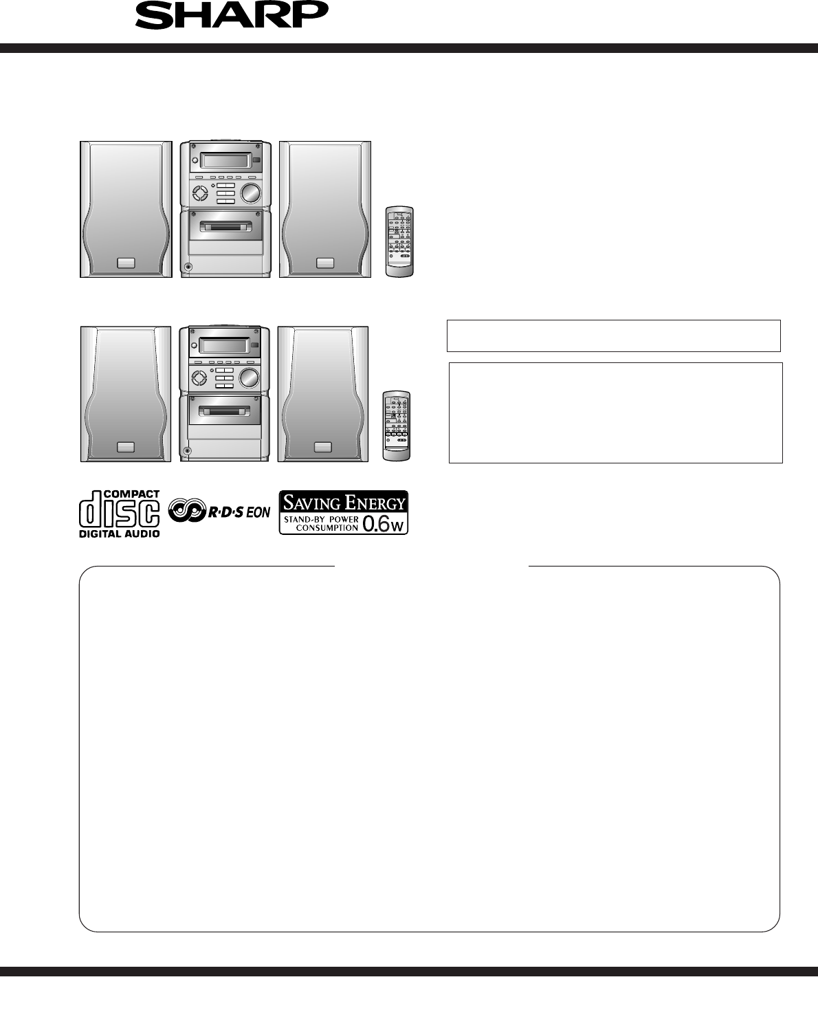
– 3 –XL-60H/70HSPECIFICATIONSXL-60H/70HCP-XL70HSpecifications for this model are subject to change withoutprior notice.CP-XL60HFOR A COMPLETE DESCRIPT
XL-60H/70H– 30 –• The numbers 1 to 17 are waveform numbers shown in page 36.ABCDEFGH123456• NOTES ON SCHEMATIC DIAGRAM can be found on page 21.F
– 31 –XL-60H/70HFigure 31 SCHEMATIC DIAGRAM (6/6)78 9 10 11 12C8430.1R8632.2KIC804 LA6541D 302928272625242322212019181716151413121110987654321R8612.2K
XL-60H/70H– 32 –Figure 32 WIRING SIDE OF P.W.BOARD (1/4)ABCDEFGH123456MAIN PWB-A1HEADPHONESPWB-A5C109R141C125C111R107C107IC102 CNP703C113R101IC101 CNP
– 33 –XL-60H/70HFigure 33 WIRING SIDE OF P.W.BOARD (2/4)78 9 10 11 1212D709D708D707D706D705D704D703D702D701SW710 SW723 BI702C773C771IC702 R787R798R799
XL-60H/70H– 34 –Figure 34 WIRING SIDE OF P.W.BOARD (3/4)ABCDEFGH123456• The numbers 1 to 17 are waveform numbers shown in page 36.F3895AF1187151
– 35 –XL-60H/70HFigure 35 WIRING SIDE OF P.W.BOARD (4/4)78 9 10 11 12BRCOLOR TABLERD(R)ORYLGRBLVLGYWH(W)BKPKBROWNREDORANGEYELLOWGREENBLUEVIOLETGRAYWHI
XL-60H/70H– 36 –WAVEFORMS OF CD CIRCUITNO DISC FOCUS SEARCH STOP PLAYFOO1 TMAX 1IC802 48pin FO+ 2SBOK2IC804 26pinIC802 12pinFO- 3 DMO 3IC804 25pi
– 37 –XL-60H/70HTROUBLESHOOTINGWhen the CD does not functionWhen the CD section does not operate when the objective lens of the optical pickup is dirt
XL-60H/70H– 38 –Make sure that the disc is normal, and set the CD TEST MODE (STEP 1).Is the measured voltage as specified in circuit diagram?Check the
– 39 –XL-60H/70H• Laser failure.Is 0V applied to the pin 57 (SEL) of IC802 ?YesNoDoes the laser come on when pattern cut between pin 8 (SEL) ofIC801 a
XL-60H/70H– 4 –NAMES OF PARTSXL-60H/70H Front panel1. Timer Indicator2. Record Indicator3. Sleep Indicator4. (CD) Random Indicator5. (CD/TUNER) Memor
XL-60H/70H– 40 –• Focus servo sawtooth wave failure.Is +6.2V applied to the pins 1 and 30 (VCC) of IC804 ? Is sawtooh wave output to the pin 48 (FOO)
– 41 –XL-60H/70H• HF error.YesYesIs output (tracking error signal) obtained at the pins 46 (TEI)and 47 (TEZI) of IC802 the CD TEST MODE "STEP 4&q
XL-60H/70H– 42 –• Sled motor operation failure.YesYesIs following sled feed signal output the pin 53 (FMO) of IC802when FF/REW key is pressed after th
– 43 –XL-60H/70HFUNCTION TABLE OF ICIC401 VHiLC75342M-1: Function/Volume Equalizer (LC75342M)1 DI Serial data and clock input pin for control.2 CE Ch
XL-60H/70H– 44 –Figure 44 BLOCK DIAGRAM OF ICIC401 VHiLC75342M-1: Function/Volume Equalizer (LC75342M)67891011 12 13 1415 16 17 18 19 202122232425265
– 45 –XL-60H/70H1-4 COM3-COM0 Output LCD common output terminal.5-7 VLC3-VLC1 — LCD power supply terminal.8 VDD — Microcomputer power supply +5V.9 OSC
XL-60H/70H– 46 –FunctionTerminal NameInput/Output54 SEG46 P63/A3 Output Electric JOG dial UP.55 SEG45 P64/A4 Output Electric JOG dial DOWN.56 SEG44 P6
– 47 –XL-60H/70HIC801 VHiTA2109F/-1:Servo Pre Amp. (TA2109F)1 VCC — Power voltage terminal2 FNI Input Main beam amp input terminal3 FPI Input Main be
XL-60H/70H– 48 –IC802 VHiTC9462F/-1: Servo/Signal Control (TC9462F) (1/3)1* TEST0 Input Test mode terminal. To be opened usually.2* /HSO Output Playba
– 49 –XL-60H/70H39 AVDD — Analog system power terminal.40 RFCT Input RFRP signal center level input terminal.41 RFZI Input RFRP zero cross input termi
– 5 –XL-60H/70HCP-XL60HXL-60H/70HCP-XL70H124312431. Tweeter2. Woofer3. Bass Reflex Duct4. Speaker Wire1. Tweeter2. Woofer3. Bass Reflex Duct4. Speaker
XL-60H/70H– 50 –83 DVDD — D/A converting section power terminal.84 DVR — Reference voltage terminal.85 LO Output L channel data forward rotation outpu
– 51 –XL-60H/70HIC804 VHiLA6541D/-1: Focus/Tracking/Spin/Sled Driver (LA6541D)In this unit, the terminal with asterisk mark (*) is (open) terminal wh
XL-60H/70H– 52 –LCD701: RV-LX0007SJZZ LCD DisplayFigure 52 LCD SEGMENTPinNo123456789101112131415161718192021com1com1z1h1g1a1RECh2g2a2SLEEPh3g3a3RANDOM
XL-60H/70HPARTS GUIDENOTE:Parts marked with “ ” are important for maintaining the safety of the set.Be sure to replace parts with specified ones for m
PRICERANKDESCRIPTIONNO.PARTS CODE NO. PARTS CODEPRICERANKDESCRIPTIONXL-60H/70H– 1 –XL-60H/70HINTEGRATED CIRCUITSIC101 VHIBA3126N/-1 J AF Head Selector
NO.PRICERANKDESCRIPTIONPARTS CODENO. PARTS CODEPRICERANKDESCRIPTIONXL-60H/70H– 2 –C209 RC-GZA476AF1C J AB 47 µF,16V,ElectrolyticC211,212 VCKYTV1HB332K
PRICERANKDESCRIPTIONNO.PARTS CODE NO. PARTS CODEPRICERANKDESCRIPTIONXL-60H/70H– 3 –C861 VCKYPA1HB102K J AA 0.001 µF,50VC862 VCKYPA1HB222K J AA 0.0022
NO.PRICERANKDESCRIPTIONPARTS CODENO. PARTS CODEPRICERANKDESCRIPTIONXL-60H/70H– 4 –R701 VRD-ST2CD103J J AA 10 kohm,1/6WR702 VRS-TV2AB103J J AA 10 kohm,
PRICERANKDESCRIPTIONNO.PARTS CODE NO. PARTS CODEPRICERANKDESCRIPTIONXL-60H/70H– 5 –SW718 QSW-K0002SJZZ J AC Switch,Key Type [SURROUND]SW721 QSW-K0002S
NO.PRICERANKDESCRIPTIONPARTS CODENO. PARTS CODEPRICERANKDESCRIPTIONXL-60H/70HACCESSORIES/PACKING PARTS (For Europe)! QACCE0001SJZZ J AH AC Power Suppl
XL-60H/70H– 6 –OPERATION MANUAL1515Notes concerning use:● Replace the batteries if the operating distance isreduced or if the operation becomes errati
XL-60H/70HABCDEFGH123456Figure 7 CD MECHANISM EXPLODED VIEW– 7 –306-1701304701302301702303NM802703x2305x2NSW801NM801305PWB-C306-2306-3306704307XL-60H
XL-60H/70HFigure 8 CABINET EXPLODED VIEWABCDEFGH123456– 8 –Note: Only the unit and consumale parts are supplied as parts supply for the Tape mechanis
XL-60H/70H– 9 –Figure 9 SPEAKER EXPLODED VIEW (1/2)ABCDEFGH123456CP-XL60H706708705701709x4702SP601(L-CH)SP602(R-CH)SP603(L-CH)SP604(R-CH)707x4703704T
XL-60H/70H– 10 –Figure 10 SPEAKER EXPLODED VIEW (2/2)ABCDEFGH123456CP-XL70H709703SP603(L-CH)SP604(R-CH)SP601(L-CH)SP602(R-CH)705707x4708x4701704x4702
XL-60H/70HPACKING OF METHOD (FOR U.K. ONLY)Setting position of switches and knobsTape Mechanism STOPCassette Holder CLOSECD Lid CLOSE1. AC Power Suppl
– 7 –XL-60H/70HPlacing the system 10 cm (4")10 cm (4")20 cm (8")10 cm (4")32Putting batteries into the remote control 1Remove the
XL-60H/70H– 8 –1 Side Panel(Left/Right)1. Screw ... (A1) x8 8-12 Top Cabinet 1. Screw ... (B1) x1 8-12. Socket ...
– 9 –XL-60H/70HFigure 9-1Figure 9-2Figure 9-31 Speaker 1. Net Frame .... (A1) x1 9-42. Front panel ... (A2) x13. Screw .....
Verwandte Produkte und Handbücher für CD Spieler Sharp X-70H
 (84 Seiten)
(48 Seiten)
(30 Seiten)
(112 Seiten)
(72 Seiten)
(88 Seiten)
(64 Seiten)
(60 Seiten)
(48 Seiten)
(90 Seiten)
(84 Seiten)
(48 Seiten)
(30 Seiten)
(112 Seiten)
(72 Seiten)
(88 Seiten)
(64 Seiten)
(60 Seiten)
(48 Seiten)
(90 Seiten)
 (16 Seiten)
(64 Seiten)
(16 Seiten)
(64 Seiten)
 (2 Seiten) (68 Seiten)
(12 Seiten)
(54 Seiten)
(124 Seiten)
(2 Seiten) (68 Seiten)
(12 Seiten)
(54 Seiten)
(124 Seiten)
© 2020, manymanuals.de. Alle Rechte vorbehalten. | 0.035 s |
 Manymanuals.com
 Manymanuals.de
 Manymanuals.fr
 Manymanuals.it
 Manymanuals.pl
 Manymanuals.cz
 Manymanuals.es
 Manymanuals-pt.com
Kommentare zu diesen Handbüchern