Sharp SF-1116 Wartungshandbuch
Stöbern Sie online oder laden Sie Wartungshandbuch nach Kopierer Sharp SF-1116 herunter. Sharp SF-1116 Service manual Benutzerhandbuch
- Seite / 125
- Inhaltsverzeichnis
- LESEZEICHEN
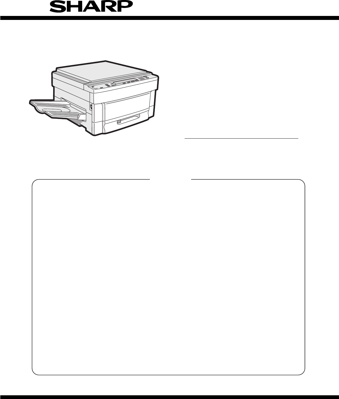
- SERVICE MANUAL 1
- Contents 2
- AND MAIN CONTROL PWB 4
- REPLACEMENT 4
- [1] PRODUCT OUTLINE 5
- [2] PRODUCT SPECIFICATIONS 6
- 3. Supply parts 7
- 4. Optional specifications 9
- <Model name: SF-S54> 10
- Staple section 10
- (4) Exclusive-use desk 10
- [3] PRODUCT VIEWS 11
- EDGE ERASE 12
- Clutches and solenoids 13
- 5. Sensors and switches 15
- 6. Rollers, mirrors, etc 16
- 1. Unpacking 17
- 2. Installation 17
- 4. Charger cleaning 19
- 5. Developing unit setting 20
- 7. Accessory installation 21
- 8. Toner supply 21
- 9. Center shift adjustment 23
- 10. Label attachment 23
- [5] DESCRIPTIONS OF EACH 24
- 2. Developing section 25
- 3. Optical section 26
- • Brightness (F8.5) 27
- • Focus: (195mm ±1%) 27
- (Copy lamp 29
- (2) Dirt correction 30
- 4. Copy process 31
- 2) Process diagram 32
- OPC drum 36
- Blade Aluminum layer 36
- Residual toner 36
- 6) Process control function 37
- Process control 38
- Process control timing 38
- Drum marking 38
- Basic structure 38
- 5. TRANSPORT/FUSING SECTION 39
- 6. Fusing paper exit section 39
- 7. High voltage section 40
- [6] DISASSEMBLY AND ASSEMBLY 41
- 1-3. PS front roller ass’y 42
- 1-4. Separation roller 42
- 2. Transport unit 43
- 3. Fusing section 44
- 3-2. Heater lamp replacement 45
- 4. Optical system 46
- Optical adjustment plate 47
- Mirror base B 49
- Mirror base positioning plate 49
- No.2/3 mirror unit 49
- Horizontal scales 50
- Projections 50
- Inscribed 51
- 6) Lens wire replacement 52
- L drive pulley 53
- Lens unit 53
- Zooming cam drive gear 54
- Notch in the optical 55
- 17 1.0 56
- 6. Process section 57
- DV cover 60
- DV blade 60
- Stirring shaft B 61
- 31T gear 61
- 9-2. Power unit 62
- 9-3. Tray size detecting PWB 62
- 9-4. Main PWB unit 63
- 9-5. AC power PWB 63
- 10. Multi paper feed unit 64
- [7] ADJUSTMENTS 65
- 2. Optical system 66
- 2-2. Note for adjustments 67
- No.4/5 drive holder 68
- Shizuoka 69
- Lens value label 70
- 1scale: 1mm 71
- 10 20 90 100 110 72
- G. Vertical skew adjustment 74
- H. Horizontal skew adjustment 74
- Mirror base rail handle 75
- Loosen Loosen 75
- 1 scale = 1mm 75
- I. Center shift adjustment 76
- K. Copy lead edge adjustment 77
- 10 20 30 78
- Scale image 79
- (2) Drum sensitivity setting 80
- UKOG-0162FCZZ 81
- COPY DENSIty 82
- Copy density adjustment 83
- Not copied Slightly copied 84
- UKOG-0110FCZZ 85
- • Grid voltage adjustment 86
- • Grid voltage check 86
- [8] SIMULATION 87
- 4. List of simulations 88
- 5. Details of simulations 89
- 0.5s 0.5s 0.5s 90
- 0.5s 0.5s 91
- 4 Set the obtained values 100
- • B ... Manual feed 101
- 6. User simulation 102
- [9] SELF DIAGNOSTICS 104
- PLACEMENT 107
- 4. Set value recording sheet 109
- 5. Memory simulation list 110
- [11] MAINTENANCE 111
- [12] ELECTRICAL SECTION 112
- Power ON 113
- 2.Main circuit 114
- SC3041K12F 115
- 4 Internal block diagram 116
- DTA123YS 119
- 1 General 120
- 2 Operation 121
- M51953 BL 122
- (11) Operation panel 123
- COPYRIGHT 125
- 1997 BY SHARP CORPORATION 125
Inhaltsverzeichnis
SERVICE MANUALCODE: 00ZSF1116/A1EMODEL SF-1116[ 1 ] PRODUCT OUTLINE . . . . . . . . . . . . . . . . . . . . . . . . . . . . . . . . . . . . . . . .
(3) 10-bin staple sorter (10-bin SS)<Model name: SF-S54>Type Copier installation type/hanging typeDistribution system Bin shift system by lead s
Main code Sub code Content48 02 Paper transport direction magnification ratio adjustmentUsed to set the horizontal (paper transport direction) magnifi
Main code Sub code Content51 02 Resist amount adjustmentUsed to set the warp amount of paper in the resist section.When this simulation is executed, w
6. User simulation This simulation allows to change and set the following setting which has been set when shipping from the factory.(1) Functions whic
(3) User simulation code tableProgramSim. codeSelection code:Set contentFactory settingAuto clear passing time setting[1][0]: Cancel[1]: 30 sec[2]: 60
[9] SELF DIAGNOSTICS1. Summary/purposeThis model has the self diag function for the following purposes:1) When a trouble occurs in the machine, the ma
Trouble code Sub code Content ConditionL1 00 Mirror feed trouble • When initializing, MHPS is not turned off within 1.5 sec fromstarting feeding of th
Trouble code Sub code Content ConditionF2 31 Image density sensor trouble • When the light emitting quantity of the image densitysensor is increased t
[10] SERVICING AT MEMORY TROUBLE AND MAIN CONTROL PWB RE-PLACEMENT1. GeneralThe EEPROM in the control PWB and the EEPROM are storingvarious set values
NOYESNOYESNOYESNOYESNOYES1Is the tonerdensity reference valuerecorded?Use Sim 43-01 to set thefusing temperatureUse Sim 22-07 to set thedeveloper repl
4. Set value recording sheetPurpose/kind SectionContentsMain code Sub code Set value DescriptionAdjustmentPaper feed section51 02 Adjustment value of
[3] PRODUCT VIEWS1. External view and internal structureNo. Name No. Name No. Name1 Original cover 2 Original table 3 Paper exit tray4 Grip 5 Manual f
5. Memory simulation listPurpose/kind SectionContentsRef. pageMaincodeSubcodeDefaultvalueDescriptionAdjustmentPaper feed section51 02 50 Adjustment va
[11] MAINTENANCE1. Maintenance cycle and maintenance itemsMaintenance of this model should be performed at every 60K.<Content> ★ = Lubricate, F
[12] ELECTRICAL SECTION 1. System block diagramGNDVD2VFMPODPWBLMMIRMVHMOCSWORSLEDKOUGAKUPWBGNDVB1VB1VD1TFDPSPSCFMMMGNDVB1GNDGND VB1VD1MMREADFGNDGNDVD1
System operation when the power is turned on:Power ONNoNoJAMRPL ONPSW ONRPL OFFInitial settingMemory transferTroubleWarm upEnd ofwarm upRacingEnd of r
8 7 6 5 432 1ABCD12345678DCBACFMPWMBLPWBLMAEDMSPROCONMMRTHDC PWBPRPR Q5PRIC20 IC14FET1IC21PCGMCGIC2IC17 IC5TM0,TM1TMTMa,TMbVFMIC10VFMPWMMHPS,LHPSAEG0,
(2) CPU (IC6) SC3041K12F1 General The CPU controls the loads of the main body and controls the systemin synchronization with data transmission and rec
4 Internal block diagramPS3/A19PS2/A18PS1/A17PS0/A16P27/A15P26/A14P25/A13P24/A12P23/A11P22/A10P21/A9P20/A8P17/A7P16/A6P15/A5P14/A4P13/A3P12/A2P11/A1P1
5 CPU SC3041K12F (IC1) pin signalPin No. Port Signal name IN/OUT H/L Specifications1 VCC VCC Power (+5V)2 P60 CVFMPWM OUT Fan motor (PWM output) signa
Pin No. Port Signal name IN/OUT H/L Specifications52 P27 AD15 Address signal53 P50 AD16 Address signal54 P51 LHPS IN L Lens home position signal (LOW
(3) Detector circuit of sensor signalThe LS151 selects one signal of D0 ∼ D7 according to the combina-tion of SEL A ∼ C signals (H, L) and outputs it
2. Operation panelNo. Name No. Name No. Name1 SORTER key and indicators 2 DUAL PAGE COPY key and indicator 3 MARGIN SHIFT key and indicator4 AUTO/MANU
(5) Heater lamp control circuit1 General The heater lamp control circuit detects the heat roller surfacetemperature with the thermistor, converts it i
[When the heat roller surface temperature is lower than the settemperature]a. Since the thermistor pin voltage is higher then the set level, theoutput
(8) AE (Auto Exposure) sensor circuitThe AE sensor circuit is composed of the AE sensor PWB; which is composed of the photo diode, the I-V convertor c
2 Operation• When "td" (= 30msec) passes after the voltage reaches 4.25V byturning on the power, the output is drive to HIGH."td"
(12) EnergyStar circuit descriptionThe EnergyStar circuit composition saves power consumption whenthe user leaves the machine with the power ON. Norma
qCOPYRIGHT 1997 BY SHARP CORPORATIONAll rights reserved.Printed in Japan.No part of this publication may be reproduced,stored in a retrieval system,
3. Clutches, solenoids, and motorsClutches and solenoidsNo. Signal name Name Functions, operations1 PSPS Paper separation solenoid Paper separation so
4. PWBNo Name Description No Name Description1 Operation PWB A Operation input, display control 2 Operation PWB B Operation input, display control3 Bl
5. Sensors and switchesNo. Signal name Name Type Operation, function1 TCS Toner density control sensor Transmission sensor HIGH when toner density fal
6. Rollers, mirrors, etc.No. Name No. Name No. Name1 No. 3 mirror 2 No. 2 mirror 3 No. 1 mirror4 Copy lamp 5 No. 4 mirror 6 No. 5 mirror7 No. 6 mirror
[4] UNPACKING AND INSTALLATION1. UnpackingPacking material/accessory listName Q’ty1 Paper exit tray 12 Instruction manual 13 Maintenance card 14 Dust
5 Avoid installation to a poorly ventilated place. 6 Avoid installation to a place where there are flammable materialsor ammonia gas, etc. If the mach
3. Optical system lock releaseA. No. 2/3 mirror unit lock releaseRemove the one fixing screw of the No. 2/3 mirror unit on the left sideof the copier.
Contents[1] PRODUCT OUTLINE . . . . . . . . . . . . . . . . . . . 1-1 1. Product features . . . . . . . . . . . . . . . . . . . . . . . . 1-1 2. S
5 Insert the main charger unit along the guide groove in the copierfully to the bottom. 5. Developing unit settingA. Developing unit setting1 Open the
6 Hold the hand carry strap of the developing unit and insert it intothe copier fully to the bottom.7 Close the developing unit lever and close the fr
3 Hold the new toner bottle as shown and shake it four or five times.4 Open the toner hopper cover.5 Pour the toner evenly into the toner hopper.6 Clo
9. Center shift adjustmentThere is basically no need to perform the center shift adjustmentbecause it is made when shipping. If the center should be s
[5] DESCRIPTIONS OF EACHSECTIONDescriptions are made on the following sections:1 Paper feed section 2 Developing section 3 Optical section4 Process se
2. Developing section 1) General descriptions(1) Two-component developerThe developer is composed of toner and carrier. Carrier serves as a medium for
3) Basic operations(Cassette paper feed)When the CPFC (cassette paper feed clutch) is turned on, the paperfeed roller shaft, the paper feed roller, an
(1) Original tableThe original table is fixed. The original is set in the left center position.(2) Copy lamp100V series: 85V, 275W200V series: 170V, 3
(7) Lens drive shaftThis shaft controls the optical axis of the lens in zoom copy. The lensfollows along the slide base shaft.(8) Lens drive wireThis
2) Basic operations(Positions of the original, the lens, and the image in each mag-nification ratio)Normal: The distance between the original set on t
1) Copy lamp replacement . . . . . . . . . . . . . . 6-6 2) Mirror base wire replacement and adjustment . . . . . . . . . . . . . . . . . . . . .
(Optical system dirt correction)This model perform dirt correction by changing the copy lamp inten-sity according to the dirt degree in the optical sy
4. Copy processThis model basic process and structure• The Scorotron method is used to evenly charge the photoconduc-tor surface to the given potentia
2) Process diagram1 Main corona unit2 Blank lamp3 Developer unit4 MG roller5 Transfer corona unit6 Separation corona unit7 Separation pawl8 Cleaning b
3) Details of image forming processStep 1 (Main Charging)By negative discharging of the main charger, uniform negative char-ges are applied to the OPC
CTLCGLOPC drumCTLCGLOPC drumLow intensity in the area corre-sponding to the darker density portion of the documentMedium intensity in the area corre-s
Step 4 (Transfer)The transfer paper is charged higher than the OPC drum surfacepotential by strong negative discharge of the transfer charger, makingt
Step 6 (Cleaning)Residual toner on the drum is removed by the cleaning blade. Theremoved toner is sent to the waste toner container by the waste toner
4) Transition of photoconductor surface potential 5) Photoconductor drum sensitivity correctionIn this model, fall in sensitivity due to long use of t
Process control1 Toner patch images are formed on the photoconductor surfaceunder the three process conditions (MC grid bias voltage). At the first pr
Waste toner transport mechanism:The waste toner is passed through wastetoner transport screw 1 and waste tonerpipe 2 to waste toner bottle 3.Waste ton
[10] SERVICING AT MEMORY TROUBLE AND MAIN CONTROL PWB REPLACEMENT . . . . . . . . . . . . . . . . . . . . . . . 10-1 1. General . . . . . . . . . .
5 Drive system divisionThe fuser unit is rotated by the main drive unit. In case of manualrotation of the fuser unit to remove paper jam, however, exc
[6] DISASSEMBLY AND ASSEMBLYThe descriptions are divided into the following sections. 1. Paper feed section 2. Transport section and power section
(Note for assembly 2)When attaching the paper feed section roller ass’y, adjust so that thepaper feed roller clutch and the PS front roller ass’y clut
(Note for assembly)Attach the paper feed roller so that the one-way clutch is on the rearframe side. (Be careful of the direction.) Attach the roller
2-2. Transport belt1 Remove the fusing unit. 2 Remove the TC case. 3 Disengage the transport belt drive shaft holder on the TC caseside, then disengag
3-2. Heater lamp replacement1 Remove the fusing cover fixing screw (1 pc.), and slide the coverto the front side to remove. 2 While pressing the Faste
3-6. Lower separation pawl replacement1 Remove the fusing unit. 2 Remove the lower heat roller, after removing the lock panel.3 Remove three screws an
Install so that the projected portion of the copy lamp is near the rearside as shown above.2) Mirror base wire replacement and adjustmentA. Copy lamp
B. Mirror base wire removal1Remove the upper cabinet L, and the left cabinet. 2 Remove the mirror wire spring from the groove on the left side ofthe o
1 Hook the metal fixture of the mirror base wire on the optical baseplate hook. 2 Pass the mirror base wire along the groove outside the doublepulley.
[1] PRODUCT OUTLINE1. Product features(1) Compact body• Compact body sizeThe body width of 600mm is the smallest in the class.• The employment of the
2 If the parallelism of the mirror base B is improper as shown in thefigure below (one side of the mirror base B is in contact with thepositioning pla
2 Remove the dark box cover upper. 3 Remove the right cabinet.4 Remember the positions of the lens drive shaft attachment plate(in the directions of A
8 Remove the drive shafts 4 and 5. * When removing the No. 4/5 mirror unit, remember the positions(scales) of the arrow marks of the drive holder 4 an
4 Remove drive spring 4 and 5.5 Remove the E-ring which is fixing the roll holder drive shaft, andremove the roll holder unit. 6 Remove the zooming ca
2. Procedures1Manually move the lens carriage unit to fit the lens carriage holewith the optical unit frame hole (which is not the home positionhole b
6 Loosen the zooming cam screw, and fit the mark of zooming camdrive gear with the mark of No. 4/5 drive shaft.* After this procedure, be sure to perf
4 Remove the screw and remove the charging plate (saw teeth)ass’y. (Cleaning/replacement and note)1 When attaching the screen grid, be careful not to
5 When installing the unit to the body, check that the groundingspring is in contact with the TC/SC case (metal section) on therear and the front side
4 While pushing waste toner bottle in the direction of A and lift itand remove. (Note for assembly/maintenance) 1As shown in the figure below, attach
6-5. Discharge lamp unit (Clean every 60K copies.)1 Remove three blue screws which are fixing the process unitholder, slide the holder and remove it.
[2] PRODUCT SPECIFICATIONS1. Basic specifications(1) Type: Table top(2) Copy speed:NormalEnlargement(Magnification)Reduction(Magnification)A3 9 shee
7. Developing section A. DV side seals F/R replacement (Replace every 120Kcopies.)1 Remove two screws which are connecting the hopper section andthe d
D. Note for toner hopper drive gear (31T) and stirringshaft attachment• Be careful of the stirring shafts A and B attachment positions. Attach so that
2 Remove the upper cabinet and the rear cabinet. 3 Remove the cooling fan from the CFM duct. (2 screws, 1 connec-tor)B. Cooling fan motorReverse the r
9-4. Main PWB unit1 Remove the rear cabinet upper. 2 Disconnect all the connectors (6 connectors) connected to themain PWB. 3 Remove the main PWB plat
10. Multi paper feed unit10-1. Separation roller1 Remove three screws and remove the paper feed/take-up rollerass’y. 2 Remove the separation roller. @
[7] ADJUSTMENTS1. Developing section1-1. Developing doctor clearance adjustmenta. If the clearance between the developing doctor and the MAGroller is
(5) Measure the distance from the marking position to the bottom(A) of the developing unit and check that the distance is17.6mm. If the distance is no
2-2. Note for adjustments1. Only the exposure balance adjustment, the blank lamp adjust-ment, and the copy lead edge adjustment can be performedindivi
2-3. Adjustment of each sectionA. Lens reference position adjustmentIn this model, the reference value according to each lens charac-teristics must be
(3) Check to confirm the lens value specified on the lens valuelabel.(4) Insert a screwdriver into hole (P) in the right rear side (paperfeed side) of
2. Description of each section(1) Paper feed sectionCopying size A3 ∼ A6/Ledger ∼ InvoicePaper feed system 1 tray + multi manual feedPaper feed capaci
(4) Calculate the copy magnification ratio.Copy magnification ratio = Copy image sizeOriginal size × 100%(5) Check that the obtained copy magnificatio
(2) Turn off/on the power to initialize the lens and No. 4/5 mirrorunit. Check the focus in the normal ratio.(3) If the focus is improper, perform the
E. Horizontal copy magnification ratio adjustmenta. This adjustment is performed to meet the displayed magnifica-tion ratio with the actual one.b. Thi
F. Comparison table of lens values and simulation input valuesLensdisplayvalueSim 48-01Zoom correction(Enlargement)Zoom correction(Reduction)Sim 48-01
G. Vertical skew adjustmenta. This adjustment is performed when a skew copy is made asshown below or when a part of the mirror base drive wire or theN
<Adjustment procedure>(1) Make an original for adjustment.Draw parallel lines at 10cm from the both edges of an A3 or11" × 17" white p
(Example) When La=12mm and Lb=9mm, shift the paper exit sidemirror base B rail upward by 1.5mm.• When Lc > Ld, shift the mirror base B rail downwar
(3) Remove the original reference plate and the right upper sidecabinet, and remove the original table glass.(4) Move the exposure plates a, b, c, and
(4) Measure the distance between the copy paper lead edge andthe copy image lead edge in each copy. Obtain RRC-A andRRC-B values from the following fo
(11) Make a normal copy and check that the image loss and thevoid amount are within the specified range.(Specified range)• Image loss: 0 ∼ 4mm• Void a
Middle & South America/Asia (excluding China)Name Content Life Product name 1 Photoconductor kit Photoconductor drum x 1Cleaner blade x 1Drum sepa
2-4. Copy density adjustmentA. When the copy density adjustment is required:The copy density adjustment must be performed in the followingcases:• When
(4) Test chart setting(1) Put several sheets of white paper (Sharp specified paper) ofabout 120mm wide and about 420mm long to the center refer-ence.(
(2) Perform the same procedures of (2) through (4) in "1) Normalmode exposure adjustment."3) Photo mode exposure adjustment(1) Press the exp
Copy density adjustmentItem ContentAutomatic exposure level initial setting 3 (Standard level)TSM mode initial setting 5 (Standard mode)AE sensor leve
Item ContentAutomatic exposure copy density adjustment Enter "0" with the 10 digit key pad.Normal modeAE1AE5TSM modeAE1 (TS)Enter "0&qu
A. Use of special measurement tools• Tool: UKOGE0043CS01 (Digital multi meter)• Electrode sheet (UKOG-0110FCZZ)AdjustmentoutputSimAdjustmentrangeF/Rdi
9 Check the drum current in the front frame side and the rear frameside. Difference between the front frame side current and the rearframe side curren
[8] SIMULATION1. OutlineThis model is equipped with the simulations feature which allows thefollowing operations with the keys on the operation panel:
4. List of simulationsMaincodeSubcodeContent101 Mirror scanning02 Optical system sensor check03 Lens operation check04 Lens operation aging201 ADF agi
5. Details of simulationsSimulation input procedure: C → ë → 0 → ëMain code Sub code Content01 01 Mirror operation checkWhen the print button is press
4. Optional specifications(1) Automatic document feeder (ADF)<Model name: SF-A18>Original set direction Face upOriginal set position Center refe
Main code Sub code Content03 02 Sorer sensor state displayThe ADF sensor ON/OFF states can be monitored with the LED on the operation panel.When the t
Main code Sub code Content06 01 PSPS operation check The separation pawl is turned on/off 30 times in the following sequence.07 01 Warm-up time displa
Main code Sub code Content21 01 Maintenance cycle settingUsed to set the lighting cycle of the maintenance lamp (è).When this simulation is executed,
Main code Sub code Content25 01 Drive system checkUsed to turn on the main motor, the developing bias, and the discharge lamp for 3 min. The input val
Main code Sub code Content26 10 AE original density settingUsed to set the original density.When this simulation is executed, the currently set origin
Main code Sub code Content30 01 Paper sensor state displayUsed to monitor the ON/OFF state of the sensors in the main body with the LED on the operati
Main code Sub code Content44 05 Grid voltage correction operation testUsed to perform the grid voltage correction and to display the measure data on t
Main code Sub code Content44 08 Grid voltage correction, optical dirt correction, drum membrane decrease correction data displayUsed to display each c
Main code Sub code Content44 10 Drum voltage correction drum surface data, patch data displayUsed to display the drum surface data and the patch data
Main code Sub code Content46 01 Exposure level adjustmentUsed to set the copy density (copy lamp output voltage) in each exposure mode.When this simul
Verwandte Produkte und Handbücher für Kopierer Sharp SF-1116
 (2 Seiten)
(144 Seiten)
(10 Seiten)
(286 Seiten)
(16 Seiten)
(14 Seiten)
(97 Seiten)
(47 Seiten)
(2 Seiten)
(4 Seiten)
(2 Seiten)
(200 Seiten)
(36 Seiten)
(108 Seiten)
(4 Seiten)
(2 Seiten)
(8 Seiten)
(2 Seiten)
(144 Seiten)
(10 Seiten)
(286 Seiten)
(16 Seiten)
(14 Seiten)
(97 Seiten)
(47 Seiten)
(2 Seiten)
(4 Seiten)
(2 Seiten)
(200 Seiten)
(36 Seiten)
(108 Seiten)
(4 Seiten)
(2 Seiten)
(8 Seiten)
© 2020, manymanuals.de. Alle Rechte vorbehalten. | 0.039 s |
 Manymanuals.com
 Manymanuals.de
 Manymanuals.fr
 Manymanuals.it
 Manymanuals.pl
 Manymanuals.cz
 Manymanuals.es
 Manymanuals-pt.com
Kommentare zu diesen Handbüchern