Sharp SF-2414 Wartungshandbuch
Stöbern Sie online oder laden Sie Wartungshandbuch nach Kopierer Sharp SF-2414 herunter. Sharp SF-2414 Service manual Benutzerhandbuch
- Seite / 131
- Inhaltsverzeichnis
- LESEZEICHEN
- SERVICE MANUAL 1
- MODEL SF-2314 1
- MODEL SF-2414 1
- MODEL SF-2514 1
- CONTENTS 2
- [1] GENERAL DESCRIPTION 4
- [2] PRODUCT SPECIFICATIONS 5
- 3. Supplies 7
- Storage period: 8
- Upper unit 9
- Lower unit 9
- 6 7 8 14 15 16 17 18 10
- 11 12 13 14 15 16 17 18 19 20 11
- 1. Packing drawing (SF-2514) 16
- 2. Installation 16
- (2) Space around the machine 17
- (3) Installing table 17
- Mirror unit fixing screw 18
- (3) Developer setting 19
- Developer unit 20
- Fixing screw 20
- (step screw) 20
- Mounting screw A 22
- Mounting screw B 22
- Mounting 23
- Multi bypass feeder unit 24
- [5] GENERAL DESCRIPTIONS OF 25
- EACH SECTION 25
- 3. Fuser, paper exit section 26
- 4. Developer section 26
- 5. Optical system 27
- 5-2. Basic operations 28
- 6. Copy process 30
- (3) Actual process 31
- Step 3 (Main Charging) 32
- Step 4 (Exposure) 32
- Step 5 (Development) 33
- Step 6 (Transfer) 34
- Step 7 (Separation) 34
- Step 8 (Cleaning) 35
- Step 9 (Discharging) 35
- (5) Process correction system 36
- 2) Correction operation 36
- [Initial setting] 37
- [Correction timing] 37
- [Correction operation] 37
- 7. SPF section (SF-2514 only) 38
- (Timing chart) 38
- [6] DISASSEMBLY AND ASSEMBLY 39
- 1-3. Separation roller 40
- One-way clutch side 41
- 1-6. Transport belt 42
- 1-7. Socket holder unit 42
- 1-8. Lower unit PWB 42
- 1-10. Power unit 42
- 2. Manual paper feed section 43
- 3. Fuser section 44
- 3-6. Scraper replacement 46
- 4. Optical system 47
- 4-6. Optical unit removal 49
- 5. SPF section 51
- 1, 2." 52
- 5-5. Clutch/solenoid removal 53
- 5-6. Sensor removal 53
- 6. Drum section 54
- 7. Developer section 54
- 7-3. Toner motor removal 55
- 7-4. Toner density sensor 55
- 9-3. Ventilation fan motor 56
- 9-1. Ozone filter 56
- 9-4. Transport roller clutch 57
- 9-5. Paper exit sensor 57
- [7] ADJUSTMENTS 58
- 0.625±0.03mm 59
- 2. Optical section 60
- Document Copy 63
- Document Copy A Copy B 64
- Cam fixing screw 65
- Do not move 65
- No.2 scanner unit 67
- Positioning plate 67
- Scanner unit drive pulley 67
- Document Copy C Copy D 68
- Change the right side 69
- Change the left side 69
- Copy paper 70
- Optical unit cover 71
- Copy image size 73
- Original size 73
- (7) Uniformity adjustment 75
- Paper exit 76
- Half-tone copy 76
- Less exposure 76
- (Dark copy) 76
- Scale image lead edge 78
- Enlargement copy (x 1.54) 78
- Reduction copy (x 0.64) 79
- Copy scale image 80
- Paper lead edge 80
- current void area (mm) 81
- 3. COPY DENSITY ADJUSTMENT 83
- Not copied 84
- Slightly copied 84
- adjustment 85
- Charger wire 87
- Improper 87
- [8] SIMULATIONS 88
- 4. Purpose list 89
- 5. Details of simulations 90
- ÷ Document length x 100 [%] 94
- EXP1~5 voltage 98
- Full power 98
- 6. User simulation 100
- Auto start function 101
- (2) User simulation prcedure 101
- (3) User program code table 102
- [9] SELF DIAG 103
- 4. Self diag contents 104
- 1) Paper feed section 109
- 2) Transport section 109
- [10] SERVICING AT MEMORY 110
- TROUBLE AND MAIN 110
- CONTROL PWB REPLACEMENT 110
- 4. Set value recording sheet 113
- 5. Memory simulation list 114
- [11] MAINTENANCE 115
- [12] ELECTRICAL SECTION 116
- M37702M2-XXXFP 117
- 3 Block diagram 118
- IN XIN IN Clock IN 119
- OUT XOUT OUT Clock OUT 119
- H=+32V, VB=+24V 120
- 1 General 121
- Stepping motor time chart 122
- External view 5P5 123
- Delay capacity 123
- V3' 124
- (1) Outline 126
- (2) Display circuit 127
- 1 Block diagram 127
- 2 Operation 127
- (3) LED display 128
- • AC PWB unit 128
- • In the main PWB unit 129
- COPYRIGHT 131
- 1997 BY SHARP CORPORATION 131
Inhaltsverzeichnis
SERVICE MANUALCODE: 00ZSF2314SM1ECopier MODEL SF-2314 MODEL SF-2414 MODEL SF-2514 [ 1 ] GENERAL DESCRIPTION . . . . . . . . . . . . . . . . . . .
2. Operation panelNo. Name No. Name No Name1Auto/manual/photo key and indicators2Light and dark keys and exposureindicators3Developer replacement lamp
6. User simulation(1) Energy saving functionThere are two specifications of energy saving: International Energy-Star specifications, and the specifica
Machine state A. Warmup B. Ready C. CopyingEnergy-saving mode Auto start from D, ED. Preheating(@1)E.Auto powershut off modeF. ResettingG. Reversed(Re
(3) User program code table[ES conforming area]ProgramPcodeSelection code:Set contentFactory settingAuto clear passingtime setting10: NO1: 30
[9] SELF DIAG1. Summary/purposeThis model has the self diag function for the following purposes:1) When a trouble occurs in the machine, the machine d
4. Self diag contentsError codeItem Description Ref. pageMain SubL1 0 Content Scanner feed trouble 8-10Detail 1) 86 pulses (45 mm) of the scanner moto
Error codeItem Description Ref. pageMain SubL4 1 Detail The rotary encoder signal cannot be detected for more than 50ms during delivery of themain mot
Error codeItem Description Ref. pageMain SubL8 3 Remedy Check the following items:1) AE sensor or its input circuit2) Copy lamp control circuit (cop
Error codeItem Description Ref. pageMain SubU2 4 Remedy Check the following items: 8-121) Main PWB EEPROM2) Memory control circuit3) Communication li
Error codeItem Description Ref. pageMain SubPC Content Personal counter installation troubleDetail The personal counter is not installed in the person
Error codeItem Description Ref. pageMain SubSPFJAM Content Document misfeed trouble 8-11Detail 1) When the document is in the SPF section, a misfeed
3. Cross section (SF-2514 as the example model)No. Name No. Name No Name1No.3 mirror2No.2 mirror3SPF transport follower roller4SPF transport roller5SP
[10] SERVICING AT MEMORYTROUBLE AND MAINCONTROL PWB REPLACEMENT1. GeneralThe control PWB stores various set values, adjustment values, andcounter valu
NOYESNOYESNOYESNOYESNOYESNOYES1Is the tonerdensity reference valuerecorded?Use Sim 43-1 to set thefusing temperatureUse Sim 21-1 to set themaintenance
NOYESNOYESNOYESNOYESNOYES2'Are the imagelead edge positionadjustment value andthe resist roller ONtiming adjustment valuerecorded?Use Sim 50-1 to
4. Set value recording sheetPurpose/kind SectionContentsMain code Sub code Set value DescriptionAdjustment Paper feed section 51 2 Adjustment value of
5. Memory simulation listPurpose/kind SectionContentsRef. pageMaincodeSubcodeDefaultvalueDescriptionAdjustment Paper feed section51 2 50 Adjustment va
Purpose/kind SectionContentsRef. pageMaincodeSubcodeDefaultvalueDescriptionSetting Fuser unit 26 13 0 Setting of the main motor operation mode in warm
[12] ELECTRICAL SECTION 1. System block diagram2. System operation at power ON1234564622 3 1 2 2 33 2 2+32V+24V+5V1+5V2FWGND31 61 6372223332222232223
3. Main circuit(1) Block diagram(2) CPU (IC110) M377021 OutlineThe M37702M2-XXXFP is a 16-bit, single-chip microprocessor whichemploys the high perfor
3 Block diagram29XIN30XOUT31E28RESET69(5V)VCC32(0V)VSS73 27 (0V)CNVSS72 (0V)AVSS70 (5V)AVCC71VREF26BYTE61 62 63 64 65 66 67 68 74 75 76 77 78 79 8
4 CPU: M37702 (IC110) pin signalsPin No. Port Signal name IN/OUT H/L Description1 P70 AES IN Analog input signal (AE sensor)2 P67 IN1 IN Lower unit se
4. Switches, sensors, detectors (The SF-2514 as the typical example)No. Abbreviation Function Type Operation1POD Paper out sensor Transmission photo s
Pin No. Port Signal name IN/OUT H/L Description56 P04 SMG OUT H Transport motor gain signal57 P03 SPPD IN H Paper entry detecting signal58 P02 KEY2 IN
(4) Heater lamp control circuit1 GeneralThe heater lamp control circuit detects the heat roller surfacetemperature with the thermistor, converts it in
(5) Driver circuit (Solenoid, magnetic clutch)1 GeneralThe control signals of each load outputted from the CPU and I/Ocannot drive the load directly.
(8) Toner supply motor drive circuitIC104 is the motor control IC which drives the toner supply motor withthe pulse signals (TMa, TMb) outputted from
(10) Copy lamp control section The change in the copy lamp exposure level is adjusted by changingthe ON period duty of the output pulse (CLPUM) from t
The copy lamp is switched by the triac. At the rising of CLPWM signal(V4), the trigger signal CL is sent to the triac to light the lamp. Thelamp will
4. Operating section (1) OutlineThe operating circuit is composed of the key matrix circuit and thedisplay matrix circuit. Key detection: Keys are det
(2) Display circuitControl is performed with the data signal and the control signal fromthe control circuit.1 Block diagram2 Operation DAta signal (8
(3) LED displayThe LED is lit up by the signal matrix of MDL0 (Q1) ∼ MDL1 (Q2) andF0 (Q3) ∼ F20 (Q23). By turning on/off ports F0 ∼ F20 with the timin
• In the main PWB unitL-732VL-832VL-5P-GNDC103470uF 63V32VCHK JPC14422000PF32V32V32VFB10524V24V24VCHK JPR101510J 1/2WQ1012SD1769D101DSS131L-6P-GNDZD10
5. Clutches, solenoids (The SF-2514 as the typical example)No. Abbreviation Name Function and operation1SRRC SPF resist roller clutch For SPF resist r
(Danish) ADVARSEL !Lithiumbatteri – Eksplosionsfare ved fejlagtig håndtering.Udskiftning må kun ske med batteriaf samme fabrikat og type.Levér det bru
qCOPYRIGHT 1997 BY SHARP CORPORATIONAll rights reserved.Printed in Japan.No part of this publication may be reproduced,stored in a retrieval system,
6. Motors (The SF-2514 as the typical example)No. Abbreviation Name Function Type1VFM Paper exit fan motorFor ventilation of the fuser unit.For coolin
7. PWBs (The SF-2514 as the typical example)No. Name Description1AC circuit PWB AC power input2Discharge lamp PWB Discharge lamp drive3Main PWB Main b
[4] UNPACKING AND INSTALLATION 1. Packing drawing (SF-2514)List of packing materials and accessoriesName Q’ty1 Packing case 12 SPF tray 14 SPF cover p
2 Avoid installation in high temperature or high humitity en-vironments. Also, avoid installation where temperature orhumidity may change quickly. (e.
(4) Power source1 The power source should be the rated voltage ±10% with thecapacity corresponding to the max. power consumption.2 Do not use an exten
Gently insert the cassette fully into the copier. (3) Developer setting1 Open the front cabinet.Push the front cabinet open buttons which are on the l
CONTENTS[ 1 ] GENERAL DESCRIPTION . . . . . . . . . . . . . . . . . . . 1-11. Features . . . . . . . . . . . . . . . . . . . . . . . . . . . . . . .
8 Install the developing unit.Slowly insert the developing unit into the copier along the guide ofthe copier until it stops.Tighten the fixing screw w
(6) Accessory attachment1 Attach the copy tray.2 Attach the document tray.[SF-2514 only]4. Locking procedure for transit orrepackingIn general, revers
5. Optional paper feed unit (SF-CM14),Installation ManualFor use with compatible SHARP copies.See SHARP copier Installation Manual to determine suitab
(4) Connect the main copier unit and the paperfeed unit.1 Secure mounting screw A (1 pc) in the main copier unit (1 loca-tion).Then, gently close the
(3) Mount the multi bypass feeder unit onto themain copier unit.1 Slide the positioning pins which project from the multi bypassfeeder unit in to the
[5] GENERAL DESCRIPTIONS OFEACH SECTION The general descriptions of the following sections are given:1 Paper feed section 2 Separation, transport sect
2. Separation, transport section After passing the resist roller section, the paper is transported to thetransfer section. After transfer, the paper i
5. Optical system5-1. General descriptions• The optical system is composed of the fixed focus lens and sixmirrors. Since the fixed focus lens is emplo
(7) Lens drive shaft This shaft is to control the optical axis of the lens in zoom copying.The lens follows on the slide base shaft.(8) Lens drive wir
(Copy lamp control in each copy density)(Optical system dirt correction)The SF-2314/2414 perform dirt correction by changing the copy lampintensity ac
4-2. Copy lamp unit replacement . . . . . . . . . . . . . . . . . 6-94-3. Mirror base drive wire replacement . . . . . . . . . . . . 6-94-4. Lens and
6. Copy process(1) Photoconductor• This model uses OPC (organic photoconductor) as photoconduc-tive material.(2) Process diagramOPC layer CTL (Electri
(3) Actual processStep 1 (charging)The OPC drum is negatively charged by corona discharge of thetransfer charger . Positive charges are generated in t
Step 3 (Main Charging)By negative discharging of the main charger, uniform negative char-ges are applied to the OPC drum surface.The OPC drum surface
Step 5 (Development)Toner is attached to the latent static-electricity images on the drumsurface to change them to visible images. The two-component m
Step 6 (Transfer)The transfer paper is charged higher than the OPC drum surfacepotential by strong negative discharge of the transfer charger, makingt
Step 8 (Cleaning)Residual toner on the drum is removed by the cleaning blade. Theremoved toner is sent to the waste toner container by the waste toner
(5) Process correction system1) Outline of the correction systemThis model is provided with the correction system for the optical unitand the photocon
2. Optical unit correction (Dirt correction)The purpose of this correction is to maintain the copy density eventhough the optical unit is contaminated
7. SPF section (SF-2514 only)1. OutlineThe SPF (Single pass feeder) is a standard provision of the SF-2514,and allows automatic copying of max. 20-she
[6] DISASSEMBLY AND ASSEMBLYThe descriptions of this chapter are divided into the following sec-tions: 1. Paper feed section, paper transport section
[1] GENERAL DESCRIPTION1. Features[Small]• Compact design• Small area for operation[Speedy]• Warm-up time 30 sec or less, the first copy 5.9 sec ∼ the
4 Remove the bearing in the rear frame and remove the paper feedroller ass’y. Note for assembly (1): Hang the roller release arm spring on thespring h
Note for assembly (1): Attach the paper feed roller so that theone-way clutch in the rear frame side. (Becareful to the installing direction.)Attach t
1-6. Transport belt1 Remove the fuser unit. 2 Remove the TC case. 3 Remove the transport belt drive shaft in the TC case from theholder, and remove th
Note for assembly (1): When attaching the harness, be careful tothe connector color and the lead wirecolor. (Carefully refer to the indication onthe
3. Fuser section 3-1. Fuser unit removal1 Open the front panel2 Remove the table glass. 3 Turn the open/close lever to the right and open the upper
3-3. Upper heat roller ass’y removal1 Remove the bearing fixing screws (2 pcs.) in the front and the rearframes. 2 Put the paper guide to the paper ex
3-6. Scraper replacement1 Remove the upper fuser unit.2 Remove the paper exit paper guide fixing screw (step screw) inthe front frame side, and remove
4. Optical system 4-1. Copy lamp replacement1 Open the body up. Release the lock lever of the manual paperfeed unit and remove the manual paper feed u
Note: After replacement of the mirror base drive wire, perform thevertical skew copy adjustment, the focus adjustment, and thehorizontal skew copy adj
Note: When the lens drive wire is removed, the magnification adjust-ment and the focus adjustment are required. 4-5. No. 4/5 mirror unit and periphera
[2] PRODUCT SPECIFICATIONS1. Basic specifications (1) Type: Table top(2) Copy speed• SF-2314Paper size Normal Enlargement ReductionB4 11 sheets/min —
3 Remove the connector and the fixing screw (1 pc.), and removethe mirror home position sensor (MHPS) towards the rear frame.4 Remove the connector an
5. SPF section 5-1. SPF mechanism removal1 Open the OC cover, and remove the SPF cover fixing screws (5pcs.). 2 Remove the SPF upper cover.3 Remove tw
5 Remove four screws from the SPF mechanism, the 2-pin connec-tor from the clutch, the 2-pin connector from the SPF coveropen/close sensor, the CN-C (
5-4. SPF control PWB replacement1 Remove the SPF upper cover as shown in "5-1-1, 2."2 Remove three connectors and two screws from the SPF co
6. Drum section 6-1. Drum unit removal1 Open the front cover. 2 While pressing down the release lever A, open the tonercartridge slowly. (Arrow B)3 Re
2 As shown in the figure below, open the section which is pressingthe cartridge pawl with a screwdriver, and pull out the developercartridge. 7-3. Ton
9. Major parts in the frame side9-1. Ozone filter1 Remove the document glass. 2 Remove the black sheet and remove the ozone filter. 9-2. Optical unit/
9-4. Transport roller clutch 1 Remove the rear cabinet. 2 Remove the transport clutch as shown in the figure below.9-5. Paper exit sensor1 Open the fr
[7] ADJUSTMENTSThe descriptions of this chapter are divided into the following sec-tions:1. Developer section (1) MG roller main pole position adjustm
(2) Adjustment of clearance between DV doctorand MG rollerIf the clearance between the DV doctor and the MG roller is improper,the following troubles
• AB seriesEach paperfeed portPaper feedsizePaper weight Special paperNo. 1 tray B4 ∼ A5(Landscape)56 ∼ 80g/m2Recommended recycle paperFrontNo. 2 tray
2. Optical section A. Adjustments listClassification No. Adjustment contentAdjustmentvalue/StandardvalueNecessaryspecial toolRef.pageParts installatio
NONOYES1'Make a test chart. (Draw a rectangle on B4 or 8 1/2" x 14" paper.)Check horizontal image distortion.The distances at the right
NOYES3'NOYESNOYESYES4Check the uniformity. Is the uniformity OK ? Put the scale to the document reference plate and set in the paper transport di
C. Adjustment contents(1) Lensa. Lens unit right angle adjustmentI. Summary By setting the optical axis of the copier body and that of the lensin para
VII. Troubles caused by improper adjustment(2) Mirror There are following adjustments of parts installation positions relatedto the mirror. *No. 4/5 m
VII. Trouble caused by improper adjustmentb. No. 4/5 mirror unit drive cam position adjustment(SF-2414/2514 only)I. Summary The copy magnification rat
Install the No. 1 and No. 2 scanner units to the specified posi-tions, adjust the mechanical horizontal parallelism, and performthe final adjustment w
6) Without moving the scanner unit drive pulley shaft, manual-ly turn the scanner unit drive pulley in the same side of theloosened setscrew. When it
10) Check the horizontal image distortion. If LL = LR, there is no horizontal distortion. LL and LR = Distance between the copyhorizontal l
VI. Adjustment procedure1) Set the test chart for image distortion adjustment on thedocument glass, and make a normal copy on a paper of A4or 8 1/2&qu
3. SuppliesSEC/SECLNo. Name Content Product name1 OPC drum kitOPC drum x 1SF234DRCleaning blade x 12 Black developerBlack developer (560g) x 10 SF
III. NoteBefore performing this adjustment, the following adjustmentmust have been completed. If not, this adjustment cannot beperformed properly. *Le
VII. Troubles caused by improper adjustment(5) Focus adjustment (Resolution adjustment)I. SummaryThe distance between the document and the photoconduc
VII. Troubles caused by improper adjustment(6) Copy magnification ratio adjustmentThe copy magnification ratio adjustment must be performed in thevert
5) Calculate the vertical copy magnification ratio.Vertical copy magnification ratio = Copy image size Original size x 100 (%)6) Check that the actua
II. PurposeThe purpose of this adjustment is to fit the displayed copy mag-nification ratio with the actual copy magnification ratio.III. Note Before
Repeat procedures 1) to 8) until the horizontal copy magnifica-tion ratio in the normal (100%) copy mode is within the specifiedrange. (SPF copy mode:
VI. Adjustment procedure1) Set a half-tone paper of A4 or 8 1/2" x 11" on the documenttable.2) Set the exposure level to the min. level in t
IV. Cases when the adjustment is required1) When the optical section is disassembled or its part isreplaced (including the scanner home position senso
5) Press the scale onto the document alignment plate and setit horizontally as shown below: 6) Execute simulations 50-1 to make several copies at e
12) Check that the difference between the distance from thecopy paper lead edge to the copy image lead edge of129% copy and that of 64% copy is in the
Environmental conditionsObserve the following environmental conditions to ensure the copyquality and machine performance. 1 Standard condition20 ∼ 25
18) Set documents in the SPF, make 100% copies, and checkthat the copy image lead edge is in the range of 0 ± 1mmfrom the paper lead edge position ref
5) Measure the lead edge void area of each copy. 6) Calculate the average void area. 7) Calculate the void area adjustment value from the formulas
5) Measure the end edge void area of each copy. 6) Calculate the average void area. 7) Calculate the void area adjustment value from the formulash
3. COPY DENSITY ADJUSTMENT(1) Copy density adjustment timingThe copy density adjustment must be performed in the followingcases:✱ When in maintenance.
3) Set the density level to "1" with the copy density adjustment key.(The currently set copy lamp voltage level will be displayed on theCOPI
2) Set the density level to "1" with the copy density adjustment key.(The currently set copy lamp voltage level will be displayed on theCOPI
(6) Copy density adjustment tableA : Auto copy mode N.TS : Non-toner-save modeP : Photo copy mode TS : Toner save modeN : Normal copy modeCopy mo
4. Others(1) Transfer charger wire installationInstall the transfer charger wire as shown below. (Clean the chargerwire at every 40K copies and replac
[8] SIMULATIONS1. OutlineThis model is equipped with the simulations feature which allows thefollowing operations with the keys on the operation panel
4. Purpose listPurpose Section Main Sub FunctionRef.pageAdjustments Paper feed section 51 2 Resist amount adjustment8-3Optical section 26 8 Copy magn
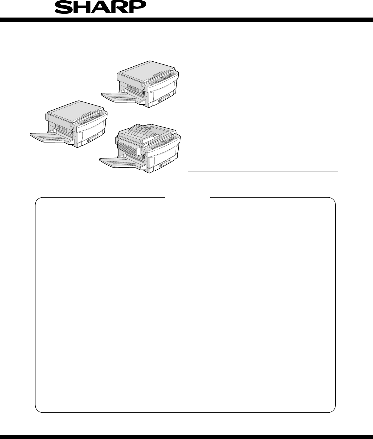
[3] EXTERNAL VIEW AND INTERNAL STRUCTURE1. External view and internal structure (SF-2514 as the example model)No. Name No. Name No. Name1Exit tray2SPF
5. Details of simulationsContentsPurpose/kind Section MaincodeSubcodeDescriptionRef. pageAdjustment Paper feedsection 51 2 Used to adjust contact pre
ContentsPurpose/kind Section MaincodeSubcodeDescriptionRef. pageAdjustment Optical unit 46 1 Used to adjust the copy density (exposure level) and the
ContentsPurpose/kind Section MaincodeSubcodeDescriptionRef. pageAdjustment Optical unit 47 Used to store the characteristics of the AE sensor and the
ContentsPurpose/kind Section MaincodeSubcodeDescriptionRef. pageAdjustment Optical unit 50 1 Used to adjust the copy image position on the copy paper
ContentsPurpose/kind Section MaincodeSubcodeDescriptionRef. pageAdjustment Developer unit 25 2 (Operation/procedure)After 3 minutes from start of sti
ContentsPurpose/kind Section MaincodeSubcodeDescriptionRef. pageSetting Specifications 26 6 Used to set the destination. (Operation/procedure)When th
ContentsPurpose/kind Section MaincodeSubcodeDescriptionRef. pageSetting Fuser unit 43 2 Used to set the fusing temperature in the power save mode.(Op
ContentsPurpose/kind Section MaincodeSubcodeDescriptionRef. pageOperationcheck Paper feed unit 30 1 Used to check the operations of the sensors and d
ContentsPurpose/kind Section MaincodeSubcodeDescriptionRef. pageOperationcheck Optical unit 1 4 Used to check the operation of the optical unit and i
ContentsPurpose/kind Section MaincodeSubcodeDescriptionRef. pageOperationcheckProcess 44 2 Used to display the reference value of the optical system
Weitere Dokumente für Kopierer Sharp SF-2414

Verwandte Produkte und Handbücher für Kopierer Sharp SF-2414
 (12 Seiten)
(32 Seiten)
(12 Seiten)
(12 Seiten)
(33 Seiten)
(116 Seiten)
(6 Seiten)
(12 Seiten)
(41 Seiten)
(100 Seiten)
(130 Seiten)
(89 Seiten)
(187 Seiten)
(104 Seiten)
(12 Seiten)
(54 Seiten)
(28 Seiten)
(98 Seiten)
(110 Seiten)
(12 Seiten)
(32 Seiten)
(12 Seiten)
(12 Seiten)
(33 Seiten)
(116 Seiten)
(6 Seiten)
(12 Seiten)
(41 Seiten)
(100 Seiten)
(130 Seiten)
(89 Seiten)
(187 Seiten)
(104 Seiten)
(12 Seiten)
(54 Seiten)
(28 Seiten)
(98 Seiten)
(110 Seiten)
© 2020, manymanuals.de. Alle Rechte vorbehalten. | 0.032 s |
 Manymanuals.com
 Manymanuals.de
 Manymanuals.fr
 Manymanuals.it
 Manymanuals.pl
 Manymanuals.cz
 Manymanuals.es
 Manymanuals-pt.com
Kommentare zu diesen Handbüchern