Sharp UX-310 Wartungshandbuch
Stöbern Sie online oder laden Sie Wartungshandbuch nach Faxgeräte Sharp UX-310 herunter. Sharp UX-310 Service manual Benutzerhandbuch
- Seite / 81
- Inhaltsverzeichnis
- FEHLERBEHEBUNG
- LESEZEICHEN
- FACSIMILE 1
- SERVICE MANUAL 1
- [1] Specifications 3
- [2] Operation panel 4
- [3] Transmittable documents 5
- [4] Installation 6
- Display shows: 7
- 5. Clearing a jammed document 9
- UX-310DE 10
- FO-730DE/NX-530DE 10
- [5] Quick reference guide 11
- (UX-3CR) 12
- CHAPTER 2. ADJUSTMENTS 13
- 1. Operating procedure 14
- 2. Diagnostic items 14
- 5. Soft switch description 17
- • Soft switch 17
- [3] Troubleshooting 29
- [4] Error code table 30
- CHAPTER 3. MECHANISM BLOCKS 31
- 1) Thermal head 32
- Drive frame 36
- Document guide upper 39
- Top cover and RP hopper 41
- Thermal head 42
- Wire treatment 43
- CHAPTER 4. DIAGRAMS 44
- [2] Wiring diagram 45
- [3] Point- to-point diagram 46
- [1] Circuit description 47
- 1. General description 48
- 2. Description of each block 48
- (1) Main control block 48
- Operation panel key scanning 51
- Operation panel LCD display 51
- INTRODUCTION 52
- FEATURES 52
- Receiving 55
- R96DFXL-CID 60
- Power supply PWB parts layout 71
- [1] Service tools 75
- 2. Description 76
- 2-1. Relay board unit 76
- 3. Shading paper 77
- 16 15 14 13 12 11 10 9 78
- 12345678 78
- 1B 2B 3B 4B 5B 6B 7B E 78
- 1C 2C 3C 4C 5C 6C 7C COM 78
Inhaltsverzeichnis
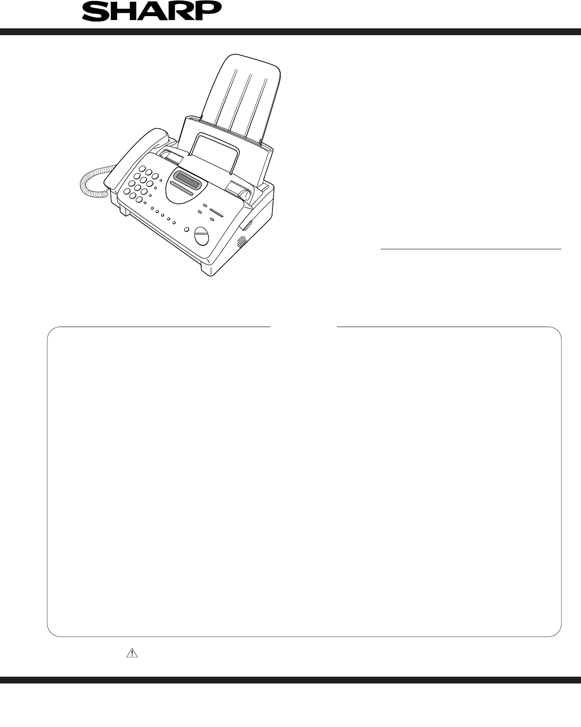
1 - 1UX-310DEFO-730DE/NX-530DEIllustration: UX-310No. 00ZUX310DESMECHAPTER 1. GENERAL DESCRIPTION[1] Specifications ...
1 – 8UX-310DEFO-730DE/NX-530DE6. Clearing jammed printing paper Pull the paper release plate forward and remove the paper. Open the operation panel (g
1 – 9UX-310DEFO-730DE/NX-530DE6. When finished, press:[5] Quick reference guideINSTALLATION1. Connect the handset as shown.2. Plug the power cord into
1 – 10UX-310DEFO-730DE/NX-530DE[6] Option imaging film specifications (UX-3CR)1. StructureThis article is composed of polyester film coated with
UX-310DEFO-730DE/NX-530DECHAPTER 2. ADJUSTMENTS[1] AdjustmentsGeneralSince the following adjustments and settings are provided for this model,make adj
UX-310DEFO-730DE/NX-530DE[2] Diagnostics and service soft switch1. Operating procedure(1) Entering the diagnostic modePress FUNC → 9 → → 8
UX-310DEFO-730DE/NX-530DE3. Diagnostic items description3. 1. Soft switch modeUsed to change the soft switch settings.The soft switch which is stored
UX-310DEFO-730DE/NX-530DE3. 12. Entry data receiveIn this mode, the registered data sent from the other machine is receiv-ed and the received data is
UX-310DEFO-730DE/NX-530DE2 – 51 Protect from echo No Yes 02 Forced 4800 BPS reception Yes No 03 Footer print Yes No 04 Length limitation of No limit C
UX-310DEFO-730DE/NX-530DE2 – 61 Auto gain control (MODEM) Enable Disable 12 End Buzzer Yes No 13 Disconnect the line when DIS is No Yes 1received in R
UX-310DEFO-730DE/NX-530DE2 – 71 DTMF signal transmission level Binary input 12 (Low) No. = 16 8 4 2 1 13 12345 04 11010 15 06 Reserved 07 Reserved 08
1 – 2UX-310DEFO-730DE/NX-530DE(Danish) ADVARSEL !Lithiumbatteri-Eksplosionsfare ved fejlagtig håndtering.Udskiftning må kun ske med batteri af samme f
UX-310DEFO-730DE/NX-530DE1 Pseudo ringer sound volume Binary input 02 No. = 8421 13 1234 04 0101 15 Reserved 06 Reserved 07 Reserved 08 Reserved 0DTMF
UX-310DEFO-730DE/NX-530DE2 – 91 Reserved 02 Reserved 03 Reserved 04 Busy tone continuous sound detect 5 sec As is PTT 1time5 Reserved 06 Busy tone det
UX-310DEFO-730DE/NX-530DE2 – 101 Reserved 02 Reserved 03 Reserved 04 Reserved 05 Reserved 06 Reserved 07 Reserved 08 Reserved 01 Reserved 02 Reserved
UX-310DEFO-730DE/NX-530DE2 – 111 Entering DIAG mode by pressing Yes No 0SPEED key2 Reserved 03 Reserved 04 Reserved 05 Reserved 06 Reserved 07 Reserve
UX-310DEFO-730DE/NX-530DE2 – 12• Soft switch function descriptionSW-A1 No. 1 Protect from echoUsed to protect from echo in reception.SW-A1 No. 2 Force
UX-310DEFO-730DE/NX-530DE2 – 13SW-A6 No. 1 Auto gain control (MODEM)When this mode is enabled, if the reception signal level is under 31dBm.The modem
UX-310DEFO-730DE/NX-530DE2 – 14SW-C1 No. 5 Line density selectionUsed to set the transmission mode which is automatically selected whenthe Resolution
UX-310DEFO-730DE/NX-530DE2 – 15SW-G2 No. 1 ~ No. 8 Off hook holdUsed to set Off hook hold time by binary input.(0 to 255 seconds)SW-G3 No. 1, No. 2 OG
UX-310DEFO-730DE/NX-530DE2 – 16SW-L1 No. 6 A4 Paper enableThe use of recording paper of A4 is enabled.SW-L1 No. 7 LEGAL and LETTER paper enableThe use
UX-310DEFO-730DE/NX-530DE2 – 17[3] TroubleshootingRefer to the following actions to troubleshoot any of problems mentionedin 1-4.[1] A communication e
1 – 1UX-310DEFO-730DE/NX-530DECHAPTER 1. GENERAL DESCRIPTION[1] SpecificationsAutomatic dialing: Rapid Key Dialing: 5 numbers(UX-310) Speed Dialing: 4
UX-310DEFO-730DE/NX-530DE[4] Error code table1. Communication error code tableG3 TransmissionCode Final received signal Error Condition (Receiver side
UX-310DEFO-730DE/NX-530DECHAPTER 3. MECHANISM BLOCKS[1] General description1. Document feed block and diagramFig. 12. Document feed operation1) The or
UX-310DEFO-730DE/NX-530DEFig. 43-5. Documents requiring use of document carrier1) Documents smaller than B6 (128mm x 182mm).2) Documents thinner than
UX-310DEFO-730DE/NX-530DE[2] Disassembly and assembly procedures• This chapter mainly describes the disassembly procedures. For the assembly procedure
UX-310DEFO-730DE/NX-530DE7 Screw (4×6) 18 AC cord ass’y 19 Screw (3×10) 210 Drive unit 111 Speaker hold spring 112 Speaker 1Fig. 2PWB’s, drive unit, A
UX-310DEFO-730DE/NX-530DEPaper roller etc. and sensor lever3Fig. 33 – 58 Platen lock bracket 19 Platen lock lever, left 110 Platen lock lever, right 1
UX-310DEFO-730DE/NX-530DE17 Reduction gear, 4 118Planet gear lever C ass’y119Planet gear lever B ass’y120 Reduction gear, 1 121 Cam hold spring 122 Ca
UX-310DEFO-730DE/NX-530DEFig. 53 – 78 CIS unit 19 CIS spring 210 Cover switch spring 111 Cover switch lever 112 Feed roller shaft 113 Feed roller 114
UX-310DEFO-730DE/NX-530DEUpper cabinet and document guideupper unitFig. 63 – 8Parts list (Fig. 6)No. Part name Q’ty No. Part name Q’ty1 Screw (3×8) 22
UX-310DEFO-730DE/NX-530DEFig. 73 – 97 Separate spring 18 Separator plate 19 Paper feed spring 110 Separator rubber 111 Guide roller 112 Document guide
1 – 2UX-310DEFO-730DE/NX-530DE[2] Operation panelJKLKURZWAHLWAHLWDH.LAUTSPR.ALPHAWAHLSTOPKOPIE/HILFESTARTLAUTSTÄRKELEISE LAUTEMPFANGSARTAUFLÖSUN
UX-310DEFO-730DE/NX-530DE19 Platen bearing, right 120 Platen roller 121 PU shaft 122 PU roller ass’y 123P-IN sensor lever spring124P-IN sensor lever12
UX-310DEFO-730DE/NX-530DETop cover and RP hopper9Fig. 93 – 119 RP release plate 110 Rotation plate 111 RP pad 112 C-spring 113 Separate plate 114 Sepa
UX-310DEFO-730DE/NX-530DEThermal head10Fig. 103 – 12Parts list (Fig. 10)No. Part name Q’ty No. Part name Q’ty1 Mechanism unit 12 Screw (3×10) 13 Head
UX-310DEFO-730DE/NX-530DEFig. 11Wire treatment113 – 13Parts list (Fig. 11)1 Screw (3×10) 12 Screw (4×6) 13 Core (F2064) 24 Core (F2063) 15 Screw (3×5)
UX-310DEFO-730DE/NX-530DE4 – 1[1] Block diagramCHAPTER 4. DIAGRAMSMODEMR96DFXL-CIDCLOCK24MHzSRAM1MbitROM2MbitCPUCPU I/FTIMERRTCPIOWATCHDOGTIMERCLOCK32
UX-310DEFO-730DE/NX-530DE[2] Wiring diagram4 – 2CAM SW26THERMAL HEADCONTACT IMAGE SENSORLCD UNITCNLCDOPERATIONPANEL PWBNUIT14CNPN16715CNCSWCNMTCNTHCNC
UX-310DEFO-730DE/NX-530DE[3] Point- to-point diagram4 – 3TX/RXMOTORTPBDTPADTPBDTPADVMTVMT1234561234567891011121314151612345678910111213141516123456789
UX-310DEFO-730DE/NX-530DECHAPTER 5. CIRCUIT DESCRIPTION[1] Circuit description1. General descriptionThe compact design of the control PWB is obtained
UX-310DEFO-730DE/NX-530DE[2] Circuit description of control PWB1. General descriptionFig. 2 shows the functional blocks of the control PWB, which is c
UX-310DEFO-730DE/NX-530DECPU Control InterfaceMIRQn 135 I HU − Modem interrupt, active low. (Hysteresis In, Internal Pullup.)SYSCLK 133 I H − System
1 – 3UX-310DEFO-730DE/NX-530DE[3] Transmittable documents1. Document Sizes* With special sizes, only one sheet can be fed into the machine at atime. I
UX-310DEFO-730DE/NX-530DEOperator Panel InterfaceOPI[2]/GPIO[23]/ 50 I/O HU 2XC (Pullup, Hysteresis In) Keyboard return [2] or GPIO[23] or SSCLK1SSCLK
UX-310DEFO-730DE/NX-530DE(2) Panel control blockThe following controls are performed by the FC100M.• Operation panel key scanning• Operation panel LCD
UX-310DEFO-730DE/NX-530DE(4) Modem (R96DFXL-CID) blockINTRODUCTIONThe Rockwell R96DFXL-CID MONOFAX modem is a synchronous 9600bits per second (bps) ha
UX-310DEFO-730DE/NX-530DER96DFXL-CID (IC6) Hardware Interface SignalsPin Signals – 100-Pin PQFPPin No. Signal Name I/O Type1 GP03 IA/OB2 GP04 IA/OB3 G
UX-310DEFO-730DE/NX-530DEHLHLCMLCI DETECTLINEEXT.HI GAINTXOUTTXMUTELHMODEM(R96DFXL-CID)CONTROL PWBTEL/LIU PWBTELTELHLEARTHHL~~+–HS AGCSIDETONECANCELER
UX-310DEFO-730DE/NX-530DE2. Noise filterThe noise filter comprises the RF choke coil, L6, L7 and L8.3. Dial pulse generation circuitThe pulse dial gen
UX-310DEFO-730DE/NX-530DE(Example: TEL speaking)NO Signal Name (CNLIUA)1 TELOUT2 TELIN3 TELMUTE4 CI/CIDIN15 CIDIN2/HS6 P-E7 P-INFig. 6Signal Name Func
UX-310DEFO-730DE/NX-530DE[4] Circuit description of power supply PWB1. Block diagram2-1. Noise filter circuitThe input noise filter section is compose
UX-310DEFO-730DE/NX-530DECHAPTER 6. CIRCUIT SCHEMATICS AND PARTS LAYOUT[1] Control PWB circuit 1/6Main control block6 – 1126435BDEFGIHCABDEFGIHCA12643
UX-310DEFO-730DE/NX-530DEMemory block 2/66 – 2126435BDEFGIHCA126435BDEFGIHCAVSSVSS1918A14217A1323 16A1215A1124 13A1025 12A9311A84A7A628A5A4A3A210A114A
1 – 4UX-310DEFO-730DE/NX-530DE7. Use of Document Carrier SheetA document carrier sheet must be used for the following documents.• Those with tears.•
UX-310DEFO-730DE/NX-530DEModem block 3/66 – 3126435BDEFGIHCABDEFGIHCA126435R120270C21368PR128270+5VD7A0C1250.01R136270D6D5D4D3D2D1D0A1A2A3A45657585960
UX-310DEFO-730DE/NX-530DESensor/Reset/Power supply block 4/66 – 4126435BDEFGIHCA126435BDEFGIHCAC2350.1R229100C2360.1(3-6D)DRSNS(3-6D)(1-5A)(1-5A)CNCSW
UX-310DEFO-730DE/NX-530DEVideo processing/Motor drive / Thermal block 5/66 – 5126435BDEFGIHCA126435BDEFGIHCA–+C2241000PC1551000PC1751000PR15422KC22910
UX-310DEFO-730DE/NX-530DEAnalog signal block 6/66 – 6126435BDEFGIHCABDEFGIHCA126435–+–+–+–+121413TELOUTCNLIUA-1R21786.6KC181680PC1781IC114053VREFTXCON
UX-310DEFO-730DE/NX-530DEControl PWB parts layout (Top side)6 – 7
UX-310DEFO-730DE/NX-530DEControl PWB parts layout (Bottom side)6 – 8
UX-310DEFO-730DE/NX-530DE6 – 9[2] TEL/LIU PWB circuit 1/2126435BDEFGIHCA126435BDEFGIHCAN.M.JP3JP1040JP101JP105Z2144JP4JP5~~+––+–++5V–+–+–++5V–++24VA+2
UX-310DEFO-730DE/NX-530DETEL/LIU PWB circuit 2/26 – 10126435BDEFGIHCA126435BDEFGIHCA+5V+24VAR14110C1260.1C1250.1C1247/25SW1HOOK SW+5VDG+24VACNLIUA-12C
UX-310DEFO-730DE/NX-530DETEL/LIU PWB parts layout (Top side)6 – 11
UX-310DEFO-730DE/NX-530DETEL/LIU PWB parts layout (Bottom side)6 – 12
1 – 5UX-310DEFO-730DE/NX-530DERemove the used film from the cartridge.Remove the four green gears from the used film.DO NOT DISCARD THE FOUR GREEN GEA
UX-310DEFO-730DE/NX-530DE[3] Power supply PWB circuit6 – 13126435BDEFGIHCA126435BDEFGIHCAC239/400D8SR140D1ERA15-06L143mHR13.3M(1/2W)V1470VF11.6A/250V
UX-310DEFO-730DE/NX-530DEPower supply PWB parts layout6 – 14
UX-310DEFO-730DE/NX-530DE[4] Operation panel PWB circuit126435BDEFGIHCA126435BDEFGIHCANote: Since the parts of PWB can not be supplied, change it as a
UX-310DEFO-730DE/NX-530DE7 – 1CHAPTER 7. OPERATION FLOWCHART[1] ProtocolNSFDISNSSTCFCEDNSFDISNSSTCFRTCMPSCFRRTCMPSMCFRTCEOPMCFMCFDCNCFRTSICSICSITSIRTC
UX-310DEFO-730DE/NX-530DE7 – 2[2] Power on sequence21YESYESCPU initializedMODEM initializedSTOP key ?“WAIT A MOMENT” displaySTARTNOYESSTAND-BY3 sec ?N
UX-310DEFO-730DE/NX-530DE8 – 1CHAPTER 8. OTHERS[1] Service tools1. ListExtension board unitNO. PARTS CODE DESCRIPTION Q’TYPRICERANK1 C P W B S 3 0 0 2
UX-310DEFO-730DE/NX-530DE8 – 22. Description2-1. Relay board unit1. Remove the TEL/LIU PWB, control PWB and Power Supply PWBfrom this unit, and mount
UX-310DEFO-730DE/NX-530DE8 – 33. Shading paperThe white and black basis is applied to remember the shading wave-form. Be sure to perform this operatio
UX-310DEFO-730DE/NX-530DE8 – 4[2] IC signal nameCONTROL PWB UNITIC5: VHiULN2003AN/ (ULN2003ANS)IC7: VHiTC74HCU04F(TC74HCU04F)IC2: VHiW24010S7LE (W2401
UX-310DEFO-730DE/NX-530DE8 – 5IC12: VHiNJM2902M-1 (NJM2902M)IC8: VHiPST596CMT1 (PST596CNR)IC4: VHi27C20012MX (27C020)EP-ROMIC10: VHiMC34119DR2 (MC3411
1 – 6UX-310DEFO-730DE/NX-530DE3. Assembly and connectionsPlug the power lead into a 220-230 V, 50 Hz, earthed (2-prong) ACoutlet.• Caution: The mains
UX-310DEFO-730DE/NX-530DE8 – 6IC6: VHiR96CiDFC1M (R96DFXL-CID)SWGAINI0VD1+5VD20VANCNCRAMPIN0VA0VD2D0D1D2D3D4D5D6GP02SWGAINORCVO0VD2RLSDnRXDGP19GP200VD
UX-310DEFO-730DE/NX-530DE8 – 7IC9: VHiR96CiDFC1M (FC100M)36A3A4A5VSSA6A7A8A9A10A11VDDA12A13A14A15A16D0D1D2D3VDDD4D5D6D7MIRQNVSSSYSCLKVSSRESETNTSTCLKDE
1 – 7UX-310DEFO-730DE/NX-530DEInsert the stack of paper into the tray, print side down.• If paper remains in the tray, take it out and combine it into
Verwandte Produkte und Handbücher für Faxgeräte Sharp UX-310
 (92 Seiten)
 (107 Seiten)
(74 Seiten)
(130 Seiten)
(28 Seiten)
(107 Seiten)
(74 Seiten)
(130 Seiten)
(28 Seiten)
© 2020, manymanuals.de. Alle Rechte vorbehalten. | 0.049 s |
 Manymanuals.com
 Manymanuals.de
 Manymanuals.fr
 Manymanuals.it
 Manymanuals.pl
 Manymanuals.cz
 Manymanuals.es
 Manymanuals-pt.com
Kommentare zu diesen Handbüchern