Sharp R-212 Bedienungsanleitung
Stöbern Sie online oder laden Sie Bedienungsanleitung nach Mikrowellen Sharp R-212 herunter. S112S01 Series S212S01 Series [en] Benutzerhandbuch
- Seite / 13
- Inhaltsverzeichnis
- LESEZEICHEN
- S112S01 Series 1
- S212S01 Series 1
- ■ Internal Connection Diagram 2
- ■ Outline Dimensions 2
- Rank mark 3
- Country of origin 3
- Date code (2 digit) 3
- ■ Absolute Maximum Ratings 4
- Model Line-up 5
- ● Standard Circuit 9
- ● Cleaning instructions 11
- ● Presence of ODC 11
- Sheet No.: D4-A02501FEN 12
- ■ Important Notices 13
Inhaltsverzeichnis
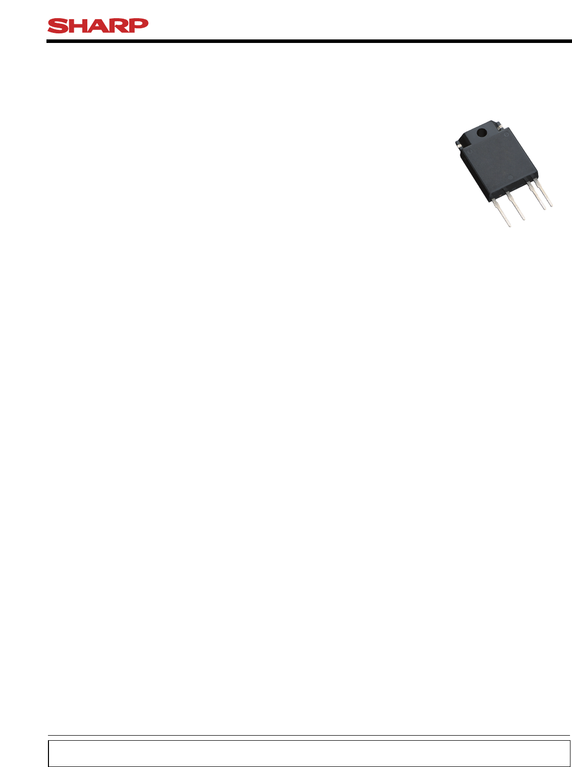
S112S01 SeriesS212S01 Series FeaturesIT(rms)≤12A, Non-Zero Cross type SIP 4pinTriac output SSR1. Output current, IT(rms)≤12.0A2. Non-zero crossing fu
Manufacturing Guidelines● Soldering MethodFlow Soldering (No solder bathing)Flow soldering should be completed below 260˚C and within 10s.Preheating
11Solvent cleaning :Solvent temperature should be 45˚C or below. Immersion time should be 3minutes or less.Ultrasonic cleaning :The impact on the devi
Package specification12Molt planePartitionPadPacking caseCushioning materialProductS112S01 SeriesS212S01 SeriesSheet No.: D4-A02501FENPackage materi
· The circuit application examples in this publication are provided to explain representative applications of SHARP devices and are not intended to gu
∗ : Do not allow external connection.( ) : Typical dimensions Internal Connection Diagram11 2 3 4234Output (Triac T2)Output (Triac T1)Input (+)Input
Date code (2 digit)Rank markThere is no rank mark indicator and currently there are no rank offered for this device.A.D.199019911992199319941995199619
Electro-optical CharacteristicsParameter Symbol UnitInputOutput(Ta=25˚C)Forward voltageReverse currentRepetitive peak OFF-state currentON-state volt
Shipping PackageModel No.Case200pcs/caseS112S01FIFT[mA](VD=12V,RL=30Ω )MAX.8400S212S01FMAX.8600VDRM[V]5S112S01 SeriesS212S01 SeriesSheet No.: D4-A0250
6S112S01 SeriesS212S01 SeriesFig.2 RMS ON-state Current vs. Ambient Temperature0605040302010Forward current IF (mA)Ambient temperature Ta (˚C)−25 1251
7S112S01 SeriesS212S01 SeriesSheet No.: D4-A02501FENRemarks : Please be aware that all data in the graph are just for reference.Fig.8-a Repetitive Pea
8S112S01 SeriesS212S01 Series Design ConsiderationsIn order for the SSR to turn off, the triggering current (lF) must be 0.1mA or less. In phase cont
9S112S01 SeriesS212S01 Series✩ For additional design assistance, please review our corresponding Optoelectronic Application Notes.● Standard CircuitT
Weitere Dokumente für Mikrowellen Sharp R-212

Verwandte Produkte und Handbücher für Mikrowellen Sharp R-212
 (42 Seiten)
(44 Seiten)
(63 Seiten)
(8 Seiten)
(21 Seiten)
(12 Seiten)
(30 Seiten)
(182 Seiten)
(143 Seiten)
(24 Seiten)
(40 Seiten)
(191 Seiten)
(52 Seiten)
(18 Seiten)
(28 Seiten)
(42 Seiten)
(44 Seiten)
(63 Seiten)
(8 Seiten)
(21 Seiten)
(12 Seiten)
(30 Seiten)
(182 Seiten)
(143 Seiten)
(24 Seiten)
(40 Seiten)
(191 Seiten)
(52 Seiten)
(18 Seiten)
(28 Seiten)
 (120 Seiten)
(7 Seiten)
(120 Seiten)
(7 Seiten)
© 2020, manymanuals.de. Alle Rechte vorbehalten. | 0.040 s |
 Manymanuals.com
 Manymanuals.de
 Manymanuals.fr
 Manymanuals.it
 Manymanuals.pl
 Manymanuals.cz
 Manymanuals.es
 Manymanuals-pt.com
Kommentare zu diesen Handbüchern