Sharp LC-60LE920UN Wartungshandbuch
Stöbern Sie online oder laden Sie Wartungshandbuch nach Fernseher & Monitore Sharp LC-60LE920UN herunter. Sharp LC-60LE920UN Service manual Benutzerhandbuch
- Seite / 80
- Inhaltsverzeichnis
- LESEZEICHEN
- SERVICE MANUAL 1
- LC-52LE920UN 1
- LC-60LE920UN 1
- SAFETY PRECAUTION 2
- II-I-I-I-I-N oooo I 2
- REMPLACER LE FUSIBLE 3
- F7000 (250V 5A) 3
- F7001 (250V 5A) 3
- Sn-Ag-Cu 4
- CHAPTER 1. SPECIFICATIONS 6
- D H_rlrH _ 7
- [2] OPERATION MANUAL 9
- CHAPTER 3. DIMENSIONS 10
- 141j2j(368) 11
- Rear Cabinet Ass'y 12
- AC Cord Cover (_ 12
- Support Cover 12
- Stand Unit 12
- MAiN Unit 13
- Speaker-R (_ 13
- _) Speaker-L 13
- POWER Unit MAIN Unit 14
- LC-52LE920UN/LC-60LE920UN 16
- SENSOR Unit 16
- AC Cord Cover __ 17
- Speaker-L 18
- POWER Unit LED Drive Unit 19
- POWER Unit 19
- MAIN Unit 19
- _¢@ @_1_(_ LCD Fixing Angle 20
- (_ Front Cabinet Ass'y 21
- [3] Caution Cleaning Glass 22
- 2. Glass cleaning 23
- ",,Glass outline 25
- CHAPTER 5. ADJUSTMENT 27
- 6. Special features 34
- 8. Signal adjustment 35
- 9. White balance adjustment 38
- 10. Key writing 39
- UPGRADE SUCCESS 40
- 1. How to start Public Mode 41
- 2. How to exit Public Mode 41
- 3. Public Mode Setting Values 41
- Setup procedure 42
- 5. On Setting Items 43
- I NO vide° 11) I 47
- I Novideo12) I 48
- I .o video 13) I 49
- I .ovideo14) I 50
- I INPUT-1Noaudio, I 53
- I Noaudio12) I 54
- I .o audio13) I 55
- I .o audio14) I 56
- ; YEs ; .o ; YEs ; .o 59
- 1. Display method 60
- 2. LED flashing method 60
- ,r-q.j-q 61
- 4. Monitor ERR STBY table 63
- [1] MAJOR IC INFORMATIONS 64
- [1] OVERALL WIRING DIAGRAM 67
- OVERALL WIRING DIAGRAM 67
- [2] SYSTEM BLOCK DIAGRAM 68
- SYSTEM BLOCK DIAGRAM 68
- PARTS GUIDE 69
- LC-52LE920UN/LC-60LE920U N 70
- [2] LCD PANEL MODULE UNIT 70
- ' 1 2 3 4 5 6 7 8 9 10 71
- [5] SUPPLIED ACCESSORIES 75
- ×3-1 ×3-2 ×3-3 75
- [81 SERVICE JIGS 79
- (USE FOR SERVICING) 79
- ALL RIGHTS RESERVED 80
Inhaltsverzeichnis
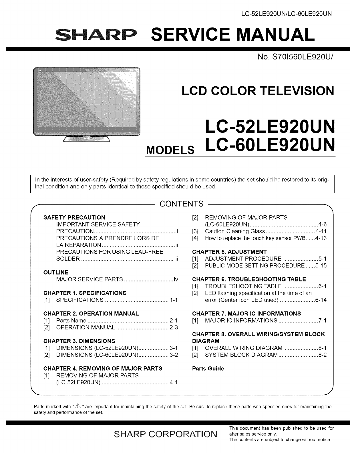
LC-52LE920UN/LC-60LE920UNSHARP SERVICE MANUALNo. S701560LE920U/LCD COLOR TELEVISIONMODELSLC-52LE920UNLC-60LE920UNIn the interests of user-safety (Requ
LC-52LE920UN/LC-60LE920UNCHAPTER 3. DIMENSIONS[1] DIMENSIONS (LC-52LE920UN)_g_d_Oo49 5/8 (1260)I459/16(1157) IO4#: I _q,IUnit: inch (mm)fl ]21 17/64 (
[2] DIMENSIONS (LC-60LE920UN)LC-52LE920UN/LC-60LE920UNUnit: inch (mm)(oLOcOo456 21/32 (1439)15 3/4 (400)LJ i _--! !e,ft ]22 27/32 (580)1 9/16 6 55/64(
LC-52LE920UN/LC-60LE920UNCHAPTER 4. REMOVING OF MAJOR PARTS[1] REMOVING OF MAJOR PARTS (LC-52LE920UN)1. Removing of Stand Unit and Rear Cabinet Ass&ap
2. Removing of Speaker-L/R.1. Remove the 2 lock screws d_ and detach the Stand Cover _.2. Disconnect SP wire.3. Detach the Speaker-L ®, Speaker-R ®.LC
LC-52LE920UN/LC-60LE920UN3. Removing of Connectors1. Disconnect the following connectors from the MAIN Unit. (SB, LB, PD, LW, RA, RL)2. Disconnect the
4. Removing1. Remove2. Remove3. Remove4. Remove5. Remove6. Remove7. Remove the8. Remove the9. Remove the10. Remove the11. Remove the12. Remove the13.
LC-52LE920UN/LC-60LE920UN5. Removing of RIO, LED Unit, ICON Unit, LOGO Unit, Front Cabinet Ass'y, Glass Front Panel Ass'y, TOUCHSENSOR Unit.
LC-52LE920UN/LC-60LE920UN[2] REMOVING OF MAJOR PARTS (LC-60LE920UN)1. Removing of Stand Unit and Rear Cabinet Ass'y.1. Remove the 3 lock screw _
LC-52LE920UN/LC-60LE920UN2. Removing of Speaker-L/R.1. Remove the 2 lock screws d) and detach the Stand Cover _).2. Disconnect SP wire.3. Detach the S
3. Removing of Connectors1. Disconnect the following connectors from the MAIN Unit. (SB, LB, PD, LW, RA, RL)2. Disconnect the following connectors fro
LC-52LE920UN/LC-60LE920UNSAFETY PRECAUTIONIMPORTANT SERVICE SAFETY PRECAUTION[] Service work should be performed only by qualified service technicians
LC-52LE920UN/LC-60LE920UN4. Removing of MAIN Unit, POWER Unit, Woofer, Stand Angle,60" LCD Panel Module Unit.1. Remove the 7 lock screws d) and d
LC-52LE920UN/LC-60LE920UN5. Removing of RIO, LED Unit, ICON Unit, LOGO Unit, Front Cabinet Ass'y, Glass Front Panel Ass'y, TOUCHSENSOR Unit.
LC-52LE920UN/LC-60LE920UN[3] Caution Cleaning Glass1. Glass handlingCAUTION: (1) As for handling, wear clean gloves, protective footwearand mask.prote
2. Glass cleaningCAUTION: (1) Visual inspection is done on the black mat.LC-52LE920UN/LC-60LE920UN(2) Dust and trash are taken with an air blow.(3) Di
LC-52LE920UN/LC-60LE920UN[4] How to replace the touch key sensor PWB1. Replace the touch key sensor PWB in a clean room.Be sure to remove the dust fro
iii) Adhere the ITO section to the front glass. (Use the positioning jig.)LC-52LE920UN/LC-60LE920UNTape fixing the FPCB and ITO sections (Adhered by t
LC-52LE920UN/LC-60LE920UNiv) Peel the protective sheet of the OCA.Lift the ITO section, then peel the protective sheet by about half by means of the p
CHAPTER 5. ADJUSTMENTLC-52LE920UN/LC-60LE920UN[1] ADJUSTMENT PROCEDUREThe adjustment values are set to the optimum conditions at the factory before sh
LC-52LE920UN/LC-60LE920UN2.2.3 How to upgrade the software1. Plug AC cord and turn on the TV.2. After picture displayed, touch the power key for 5seco
LC-52LE920UN/LC-60LE920UN2.3. Monitor microprocessor software version upgradeCreate the USB memory for monitor microprocessor software version upgrade
PRECAUTIONS A PRENDRE LORS DE LA REPARATIONLC-52LE920UN/LC-60LE920UN• Ne peut effectuer la r_paration qu' un technicien sp_cialis6 qui s'est
LC-52LE920UN/LC-60LE920UN3. Entering and exiting the adjustment process mode1) Before entering the adjustment process mode, the AV position RESET in t
LC-52LE920UN/LC-60LE920UN5. List of adjustment process mode menuThe character string in brackets [ ] will appear as a page title in the adjustment pro
LC-52LE920UN/LC-60LE920UNPage Line Item7 1 ANALOG RGB ADJ2 R A GAIN3 G A GAIN4 B A GAIN5 R OFFSET6 G OFFSET7 B OFFSET8 1 VCOM ADJ9 1 LEV12 LEV23 LEV34
Page Line14 1 CAL C2 RESET3 VAL14 VAL25 VAL36 VAL47 VAL58 VAL615 1 MONITOR TIME OUT2 MONITOR MAX TEMP3 MONITOR ERROR CAUSE RESET16 1 LCD TEST PATTERN2
LC-52LE920UN/LC-60LE920UNPage2324Line Item1 ERROR STANDBY CAUSE12 ERROR STANDBY CAUSE23 ERROR STANDBY CAUSE34 ERROR STANDBY CAUSE45 ERROR STANDBY CAUS
LC-52LE920UN/LC-60LE920UN7. Microprocessor software writing7.1. Main microprocessor/monitor microprocessor software writing (Main PWB: QPWBXF452WJZZ)A
LC-52LE920UN/LC-60LE920UN[] Signal generator level adjustment check (Adjust to the standard value level.)•Composite signal:• 15K component signal:•33K
8.2.6 Analog RGB signal adjustmentLC-52LE920UN/LC-60LE920UNAdjustment pointSettingAdjustment conditionsSignal: XGA(1024x768) 60HzSYNC: HV separateAdju
LC-52LE920UN/LC-60LE920UN9. White balance adjustment9.1. White balance adjustment (For details about the adjustment procedure, refer to "Kameyama
LC-52LE920UN/LC-60LE920UNAdjustment Adjustment conditions Adjustment procedurepoint[Adjustment standard value]Measuring instrument: [Minolta CA-210] T
LC-52LE920UN/LC-60LE920UNPRECAUTIONS FOR USING LEAD-FREE SOLDER='Employing lead-free solder"PWBs" of this model employs lead-free solde
LC-52LE920UN/LC-60LE920UN11. Factory settingAfter completing the factory setting, pull out the AC cord to complete the setting.CAUTION: Do not turn on
[2] PUBLIC MODE SETTING PROCEDURE1. How to start Public Mode• There are the following 3 ways to get the public mode setup screen displayed.In the adju
LC-52LE920UN/LC-60LE920UN4. Public Mode MenuThe guidance is not displayed on screen.Setup procedure• To move the cursor up and down, use the "cur
5. On Setting Items* "EZ-SETUP" discussed below indicates "EZ-SETUP after the first power-on".LC-52LE920UN/LC-60LE920UN1) POWER ON
LC-52LE920UN/LC-60LE920UN6) PANEL BUTTONSelection Selection between "Respond" and "No respond" (loop provided)Default RespondExpla
LC-52LE920UN/LC-60LE920UN10)INPUT MODE FIXEDSelectionDefaultExplanationLimit in SettingExceptionRemarks11)RC_PATH_THROUGHSelection Selection between &
LC-52LE920UN/LC-60LE920UN15)PUBLIC MODE (ON!OFF)Selection Selection between "ON" and "OFF" (loop provided)Default OFFExplanation I
CHAPTER 6. TROUBLESHOOTING TABLELC-52LE920UN/LC-60LE920UN[1] TROUBLESHOOTING TABLEI NO vide° 11) II COMPOSITE: No external input video IINPUT-2] ...
LC-52LE920UN/LC-60LE920UNI Novideo12) II COMPONENT: No external input video IINPUT-1] ... IIs INPUT-] selected on the input select menu screen?Is the
LC-52LE920UN/LC-60LE920UNI .o video 13) II No video at UHFNHF broadcast si_lnal reception II Is the specified TV signal selected on the input select m
OUTLINELC-52LE920UN/LC-60LE920UNMAJOR SERVICE PARTSmPWB UNITRef No. Part No. DiscriptionN DKEYMF452FM20 MAIN Unit*lN DUNTKF493FM01 ICON UnitN DUNTKF49
LC-52LE920UN/LC-60LE920UNI .ovideo14) II PC: No external input video [INPUT-3] II Is INPUT-3 selected on the input select menu screen? I_' NOSele
LC-52LE920UN/LC-60LE920UNI <HDMI input> No video 15)-1 II HDMI: No external input video [INPUT-4] IIs INPUT-4 selected on the input select menu
LC-52LE920UN/LC-60LE920UNI <HDMI input> No video 15)-2 II HDMI: No external input video [INPUT-6] IIs INPUT-6 selected on the input select menu
LC-52LE920UN/LC-60LE920UNI Noaudio11) II INPUT-1Noaudio, I[ Is INPUT-1 selected on the input select menu screen? ]€I INPUT-2 No audio, I¢Is INPUT-2 se
LC-52LE920UN/LC-60LE920UNI Noaudio12) II [PC analo_l audio input] INPUT-3 No audio, IIs INPUT-3 selected on the input select menu screen?I [HDMI analo
LC-52LE920UN/LC-60LE920UNI .o audio13) II No audio at UHFNHF broadcast si_lnal reception, II Is TV selected on the input select menu screen? II No aud
LC-52LE920UN/LC-60LE920UNI .o audio14) II INPUT-4 No audio IHDMI connected IINPUT-5 No audio IHDMI connected IINPUT-6 No audio IHDMI connected IINPUT-
LC-52LE920UN/LC-60LE920UNI No audio si_lnal at Di_lital Audio Output terminal IAnalo_l sound heard I II NoINPUT-4151617IHDMI)audio. IIf no video appea
LC-52LE920UN/LC-60LE920UNI No monitor audio output I[ Is the audio output from the monitor set at "VARIABLE" or "FIXED" on the men
LC-52LE920UN/LC-60LE920UNI If it is not an error of power supply/LED driver,It is start-up in the lamp error disre_lard mode,II Do you start? I_'
LC-52LE920UN/LC-60LE920UNCHAPTER 1. SPECIFICATIONS[1] SPECIFICATIONSLCDpanelTVFunctionAudio outBack panelverticalinputsTerminalsBack panelhorizontalin
LC-52LE920UN/LC-60LE920UNi Trouble Shootin_l Panel Module iWhen C-S FPC(2 pieces) is replaced, does screen display normally? ]; YES[ Replace C-S FPC(2
Table 1. Concrete flashing patternItemInverter/Lamp system failurePower PWBfailure(Power failure, etc.)Main PWBfailure(Communicationfailure, etc.)Othe
LC-52LE920UN/LC-60LE920UNLED flashing timing chart at the time of an error100ms 400ms 1.6sec1) Inverter/Lamp failure details (Flashes slowly once and
4) Other failure details (Flashes slowly 4 times and flashes fast)Error typeMonitor temperaturefailureFlashes fast onceMain failureFlashes fast 3 time
LC-52LE920UN/LC-60LE920UNCHAPTER 7. MAJOR IC INFORMATIONS[1] MAJOR IC INFORMATIONS1. MAJOR IC INFORMATIONS1.1. IC1504 (VHiSii9287+-1Q)This IC is 4 inp
LC-52LE920UN/LC-60LE920UN1.10. IC2701 (VHiYSS951VZ-lY)Audio DSP (YSS951VZ) has digital audio adjustment function (for example, PEQ, bass/treble, balan
LC-52LE920UN/LC-60LE920UN-- MEMO --7-3
CHAPTER 8. OVERALL WIRING/SYSTEM BLOCK DIAGRAMLC-52LE920UN/LC-60LE920UN[1] OVERALL WIRING DIAGRAMOVERALL WIRING DIAGRAMifWOOFER: RSP-ZA482WJZZPOWER Un
LC-52LE920UN/LC-60LE920UN[2] SYSTEM BLOCK DIAGRAMSYSTEM BLOCK DIAGRAMINPUT3/4tC2701DSP(YSS951)_NPUT DDC06 HDMi0INPUT DbC15 NDMII IC1504HDM_SWSH9287DDC
LC-52LE920UN/LC-60LE920UNSHARP PARTS GUIDENo. S701560LE920U/LCD COLOR TELEVISIONMODELSLC-52LE920UNLC-60LE920UNfCONTENTS[1] PRINTED WIRING BOARDASSEMBL
CHAPTER 2. OPERATION MANUALLC-52LE920UN/LC-60LE920UN[1] Parts NameCenter Ic°n illumin!ti°n"_ _" !Remote control sensorOPC sensor "IVOL-
LC-52LE920UN/LC-60LE920U NPRICE NEW PARTNO. PARTS CODE RANK MARK DELVERY[1] PRINTED WIRING BOARD ASSEMBLIESz_NNNNNNNNNDESCRIPTIONDKEYMF452FM20 BWDUNTK
[3] CABINET PARTS (LC-52LE920UN)LC-52LE920UN/LC-60LE920UN' 1 2 3 4 5 6 7 8 9 10
LC-52LE920UN/LC-60LE920U Nz_PRICE NEW PARTNO. PARTS CODE RANK MARK DELVERY[3] CABINET PARTS (LC-52LE920UN)DESCRIPTION1I-II-2I-3I-4I-5I-6I-722-12-22-32
[4] CABINET PARTS (LC-60LE920UN)LC-52LE920UN/LC-60LE920UN@[]LOGO] UnitR/C,[]SENSORUnite_®>[][][]\60" LCD @ iPanel @Module Unit@' 1 2 3 4
LC-52LE920UN/LC-60LE920U NA_PRICE NEW PARTNO. PARTS CODE RANK MARK DELVERY[4] CABINET PARTS (LC-60LE920UN)1I-I1-21-31-41-51-61-722-I2-22-32-42-52-62-7
[5] SUPPLIED ACCESSORIESLC-52LE920UN/LC-60LE920UNX5Remote control unit(x 1)X4X13"AAA"size battery(x 2)X12Cable clamp(x 1)Xll Connection guid
LC-52LE920UN/LC-60LE920U N[6] PACKING PARTS (NOT REPLACEMENT ITEM) (LC-52LE920UN)X5S8 X9X6 XIOX8 XI 1$4S10X3X4$4$4$17$3$5$6XI$5$5$5S2\I'k Not Rep
PRICE NEW PARTNO. PARTS CODE RANK MARK DELVERY[6] PACKING PARTS (NOT REPLACEMENT ITEM) (LC-52LE920UN)$1$2$3$4$5$6$7$8$9$10$11LC-52LE920UN/LC-60LE920UN
LC-52LE920UN/LC-60LE920UN[7] PACKING PARTS (NOT REPLACEMENT ITEM) (LC-60LE920UN)_S8X6X8X9x5_t¢[._,ii1_$1o_rS7_$1o_r $7I _r Not Replacement item I10
LC-52LE920UN/LC-60LE920UNNO. / PARTS CODE I PRICEI NEW I PART IL[7] PACKING PARTS (NOT REPLACEMENT ITEM) (LC-60LE920UN)DESCRIPTION$1 SPAKCF782WJZZ$2 S
LC-52LE920UN/LC-60LE920UN1I 18° 19TV STB DVD'VCR AUDIO3_OREC4 OPTION SLEEP PAOIWEGR 205 _ ...21
LC-52 LE920 U N/LC-60 L E920 U NSHARPCOPYRIGHT © 2010 BY SHARP CORPORATIONALL RIGHTS RESERVED.No Part of this publication may be reproduced,stored in
[2] OPERATION MANUALLC-52LE920UN/LC-60LE920UN° Before attaching (or detaching) the stand, unplug the AC cord.• Before performing work spread cushionin
Verwandte Produkte und Handbücher für Fernseher & Monitore Sharp LC-60LE920UN
 (50 Seiten)
 (96 Seiten)
© 2020, manymanuals.de. Alle Rechte vorbehalten. | 0.077 s |
 Manymanuals.com
 Manymanuals.de
 Manymanuals.fr
 Manymanuals.it
 Manymanuals.pl
 Manymanuals.cz
 Manymanuals.es
 Manymanuals-pt.com
Kommentare zu diesen Handbüchern