Sharp AR-650 Wartungshandbuch
Stöbern Sie online oder laden Sie Wartungshandbuch nach Multifunktionsgeräte Sharp AR-650 herunter. Sharp AR-650 Service manual Benutzerhandbuch
- Seite / 396
- Inhaltsverzeichnis
- LESEZEICHEN

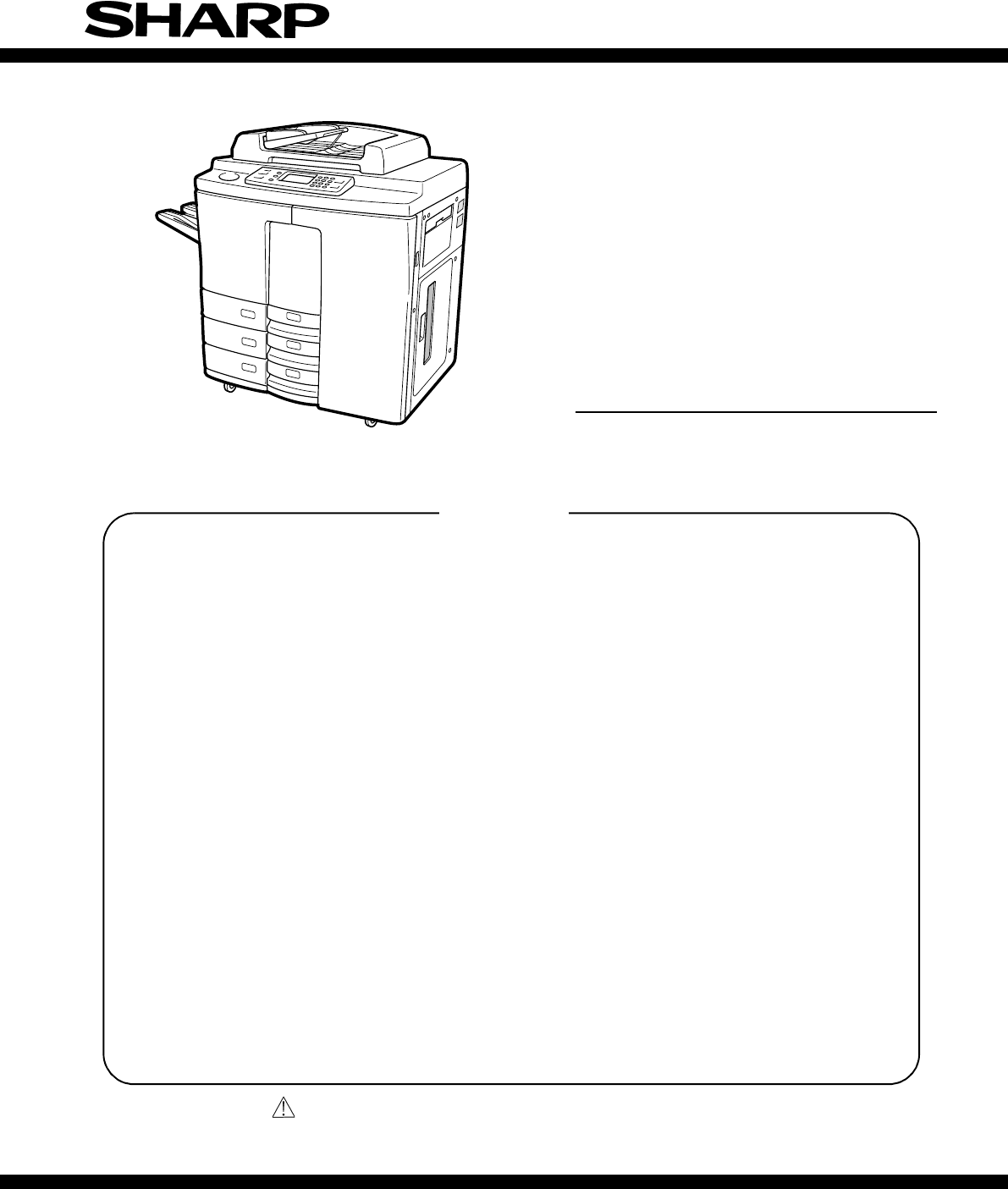
- SERVICE MANUAL 1
- DIGITAL COPIER 1
- AND SERVICE FOR THE COPIER 2
- CONTENTS I 4
- II CONTENTS 5
- CONTENTS III 6
- CONTENTS IV 7
- CONTENTS V 8
- CONTENTS VI 9
- 1.1 Specifications 10
- SPECIFICATIONS 1 - 2 11
- 1 - 3 SPECIFICATIONS 12
- SPECIFICATIONS 1 - 4 13
- 1 - 5 SPECIFICATIONS 14
- SPECIFICATIONS 1 - 6 15
- 1 - 7 SPECIFICATIONS 16
- SPECIFICATIONS 1 - 8 17
- 1 - 9 SPECIFICATIONS 18
- SPECIFICATIONS 1 - 10 19
- 1 - 11 SPECIFICATIONS 20
- USA/CANADA 21
- OTHER COUNTRY 21
- 1.5 System List 22
- 2. OUTLINE OF THE MACHINE 23
- OUTLINE 2 - 2 24
- 2 - 3 OUTLINE 25
- [B] Front Drive System 26
- [C] Rear Drive System 27
- OUTLINE 2 - 6 28
- 2 - 7 OUTLINE 29
- Scanner unit 30
- Laser unit 30
- System unit 30
- [LT series] 32
- (B-3) Motors 33
- (B-4) AC electrical parts 33
- [C] Laser Unit 34
- (C-1) PC boards 34
- (C-3) Motors 35
- [D] System Unit 35
- (D-1) PC boards 35
- No. Name Symbol 38
- Upper unit 39
- OUTLINE 2 - 18 40
- (F-3) Motors 41
- (F-4) AC electrical parts 42
- Lower unit 43
- (G-3) Motors 45
- (G-4) AC electrical parts 46
- (1) Motors 47
- (2) Solenoids 48
- (4) Counters 48
- (5) Switches 48
- 2 - 27 OUTLINE 49
- (6) Heaters and lamps 50
- (7) PC boards 50
- (8) Transformers 51
- (9) Other 51
- 2.3 System Block Diagram 52
- Lower front cover 53
- Power switch cover 54
- 2 - 33 OUTLINE 55
- Rear top cover 56
- Original glass 56
- Lock supports 58
- High - voltage transformer 58
- Ground wire fixing screw 58
- Power inner cover 59
- 3. COPYING PROCESS 62
- COPYING PROCESS 3 - 2 63
- 3 - 3 COPYING PROCESS 64
- COPYING PROCESS 3 - 4 65
- 3 - 5 COPYING PROCESS 66
- Aluminum 67
- Photosensitive layer 67
- Discharge LED array 69
- 3 - 9 COPYING PROCESS 70
- COPYING PROCESS 3 - 10 71
- 4. COPIER OPERATION 72
- COPIER OPERATION 4 - 2 73
- 4 - 3 COPIER OPERATION 74
- COPIER OPERATION 4 - 4 75
- 4 - 5 COPIER OPERATION 76
- COPIER OPERATION 4 - 6 77
- 1.144sec 78
- Exit switch 79
- CLEAR PAPER (E02) 79
- 4 - 9 COPIER OPERATION 80
- 4.4.1 Power ON to ready 81
- 4 - 11 COPIER OPERATION 82
- 4.4.2 Automatic feed copying 83
- 4 - 13 COPIER OPERATION 84
- 5 - 1 DISPLAY UNIT 85
- DISPLAY UNIT 5 - 2 86
- 5 - 3 DISPLAY UNIT 87
- DISPLAY UNIT 5 - 4 88
- 5 - 5 DISPLAY UNIT 89
- 5.4 Description of Operation 91
- DISPLAY UNIT 5 - 8 92
- 5 - 9 DISPLAY UNIT 93
- KEY boardLCDLCD board 94
- Semicon 95
- 6.2 Image Processing Circuit 96
- 6 - 3 IMAGE PROCESSING 97
- Histogram 98
- 6 - 5 IMAGE PROCESSING 99
- IMAGE PROCESSING 6 - 6 100
- 6 - 7 IMAGE PROCESSING 101
- 6.4 PLG Board (PWA-F-PLG-300) 102
- 6.5 Scanner 103
- 6.6 Printer 103
- 7.1 Functions 104
- Reflector Original Glass 105
- Reflector 105
- Exposure lamp 105
- Mirror 1 105
- Carriage 2 106
- Copiable length 107
- Original indicator unit 107
- Carriage 1 107
- Copiable width 107
- Optical System (rear side) 108
- SCANNER 7 - 6 109
- 7 - 7 SCANNER 110
- Fig. 7.4-4. PWA-SDV 111
- 7.5 Exposure Control Circuit 112
- SCANNER 7 - 10 113
- 1 to generated 114
- SCANNER 7 - 12 115
- 7.6 Outline of Control 116
- Fig. 7.7-1 117
- [A4 Series] [LT Series] 117
- [A4 Series] 118
- [LT Series] 118
- SCANNER 7 - 16 119
- Original 120
- Phototransistor 120
- [A4 series] 121
- APS cover 122
- Scanning motor 123
- Connector 123
- Optical fan 124
- Front top frame 125
- Rear top frame 125
- Mirror 2 126
- Mirror 3 126
- Installation standard 127
- Setting holes 127
- 7 - 25 SCANNER 128
- 8. PRINTING 129
- Feed side 130
- Exit side 130
- Front side 130
- Rear side 130
- PLG PCboard 130
- 8.2 Structure 131
- (3) Half mirror 132
- 8 - 5 PRINTING 133
- PRINTING 8 - 6 134
- 8 - 7 PRINTING 135
- 8.3 Laser Diode 136
- 8 - 11 PRINTING 139
- 9. PAPER FEED SYSTEM 140
- PAPER FEED SYSTEM 9 - 2 141
- Construction of motor drive 142
- PAPER FEED SYSTEM 9 - 4 143
- 9.2 Aligning Section 144
- Aligning roller (L) 145
- Paper guide 145
- Set screw 146
- Aligning motor 146
- Belt transport unit 147
- 9 - 9 PAPER FEED SYSTEM 148
- PAPER FEED SYSTEM 9 - 10 149
- 9 - 11 PAPER FEED SYSTEM 150
- (1) Tray section 151
- (2) Paper feeding section 152
- PAPER FEED SYSTEM 9 - 14 153
- Pick-up bracket 154
- Manual pick-up roller 154
- LCF pick-up roller 155
- 9 - 17 PAPER FEED SYSTEM 156
- Paper-feed roller 157
- Separation roller 157
- 9 - 19 PAPER FEED SYSTEM 158
- PFP paper feed guide unit 159
- Drive bracket 159
- — Outer side Upper side 160
- Tray motor 161
- Tray motor unit 161
- Bottom switch unit 162
- Guide lever 162
- PAPER FEED SYSTEM 9 - 24 163
- LCF feed roller 164
- LCF separation roller 164
- 9.4 Paper Feed Pedestal (PFP) 168
- 9.4.2 Component names 169
- 9 - 31 PAPER FEED SYSTEM 170
- PAPER FEED SYSTEM 9 - 32 171
- Internal signals 172
- 9 - 35 PAPER FEED SYSTEM 174
- PAPER FEED SYSTEM 9 - 36 175
- Have two seconds 179
- CW came ON? 179
- 9 - 41 PAPER FEED SYSTEM 180
- PAPER FEED SYSTEM 9 - 42 181
- 9 - 43 PAPER FEED SYSTEM 182
- PAPER FEED SYSTEM 9 - 44 183
- 9 - 45 PAPER FEED SYSTEM 184
- Cassette switch 185
- Cassette 185
- Actuator 185
- (the actuator is detected) 186
- PAPER FEED SYSTEM 9 - 48 187
- PFP pick-up rolle 189
- Gear E-ring 190
- Stay guide 191
- Switch cover 192
- PFP tray-up switch 192
- PFP paper empty switch 192
- PFP upper aligning roller 193
- (metal roller) 193
- (rubber roller) 193
- Motor fixing screws 194
- Gear units 194
- (Outside) (Inside) 195
- 10. DRUM-RELATED SECTION 196
- 10.2 Functions 197
- Thermistor bracket 198
- Drum thermistor 198
- Front flange 199
- Charge wire 200
- V-groove 200
- Wire cleaner 201
- Main charger cleaning motor 202
- Ozone filter 203
- (2 screws) 205
- 11. TRANSFER/TRANSPORT UNIT 206
- 11.2 Description of Operation 207
- 11.3 Functions 208
- [Right side] 210
- [Left side] 210
- Front frame side cam 211
- Front side lever 211
- (Silver PCboard) 214
- (Green PCboard) 214
- Locking support 215
- 12. DEVELOPER UNIT 216
- 12.2 Construction 217
- 12 - 3 DEVELOPER UNIT 218
- Sensor lever 219
- Developer Unit Drive 221
- 12.4 Motors 222
- DEVELOPER UNIT 12 - 8 223
- Signal “H” level “L” level 224
- DEVON Motor OFF Motor ON 224
- Toner motor 225
- Gate array 225
- 12 - 11 DEVELOPER UNIT 226
- DEVELOPER UNIT 12 - 12 227
- ATS: large 228
- ATS: small 228
- Developer unit 229
- Top cover 229
- Urethan seal 230
- Guide roller 231
- Magnetic roller holder 232
- Magnetic roller 232
- Pole fixing holder 232
- Magnet roller holder 233
- Transport roller 234
- Pole fixing bush 234
- Convex part of sideframe 234
- Nozzle mixer 235
- Oil seal 235
- Mixer shaft 236
- Toner hopper unit 238
- Motor bracket 239
- Motor unit 240
- Developer bias 240
- DEVELOPER UNIT 12 - 26 241
- DEVELOPER UNIT 12 - 28 243
- 13. CLEANER UNIT 244
- 13.2 Description of Functions 245
- 13 - 3 CLEANER UNIT 246
- CLEANER UNIT 13 - 4 247
- Toner adhesion amount sensor 248
- Photosensitive drum 248
- Test pattern (toner image) 248
- Light source intensity signal 248
- CLEANER UNIT 13 - 6 249
- 13 - 7 CLEANER UNIT 250
- Recovery blade 252
- Fur brush 252
- Separation claw unit 253
- Solenoid 255
- Bunding band 255
- Toner bag 256
- Toner bag cover 256
- Toner-full detector 256
- CLEANER UNIT 13 - 14 257
- Fig. 14.1-1 258
- 14.3 Functions 259
- 14 - 3 FUSER UNIT 260
- 14.4 Heater Control Circuit 261
- Reference 262
- Fig. 14.5-1 264
- HTRMOT Motor OFF Motor ON 265
- 1mm~1.5mm 267
- Harness cover 268
- Lower thermistor 268
- Jam release unit 268
- Separation claw 269
- Lower separation claw unit 269
- 14 - 13 FUSER UNIT 270
- Stop ring 271
- Timing belt 271
- Upper heat 272
- Pressure lever 273
- Lower heat roller 273
- Stamped mark 273
- Lower inlet guide 273
- Connector cable bracket 274
- Heater fan 276
- 15.1 Introduction 277
- ADU 15 - 2 278
- 15.2 Drive 279
- Paper side guide 280
- Paper trailing edge guide 280
- Width guide motor 280
- Length guide motor 280
- Holding gate 281
- Spring clutch 281
- Flapper solenoid 281
- Aligning roller 281
- Aligning clutch 281
- 15.3 Description of Operation 282
- 15 - 7 ADU 283
- ADU 15 - 8 284
- 15 - 9 ADU 285
- ADU 15 - 10 286
- Length guide switch 287
- Width guide switch 287
- Position detection switch1 287
- ADU 15 - 12 288
- 15 - 13 ADU 289
- ADU 15 - 14 290
- 15 - 15 ADU 291
- Feed switch 292
- Aligning switch 292
- Color (black-black) 293
- (white-white) 293
- (white-black) 293
- ADU 15 - 18 294
- Transport guide-u 295
- ADU 15 - 20 296
- Discharge brush 297
- Exit roller 299
- Transport / reverse 300
- 16.1 Outline 301
- 16.2.1 ADF construction 302
- 16 - 3 ADF 303
- 16 - 5 ADF 305
- ADF 16 - 6 306
- 16 - 7 ADF 307
- ADF 16 - 8 308
- 16 - 9 ADF 309
- ADF 16 - 10 310
- 16 - 11 ADF 311
- ADF 16 - 12 312
- 16 - 13 ADF 313
- ADF 16 - 14 314
- 16 - 15 ADF 315
- ADF 16 - 16 316
- 16 - 17 ADF 317
- ADF 16 - 18 318
- 16 - 19 ADF 319
- ADF 16 - 20 320
- 16.5 Detection of Paper Jam 321
- ADF 16 - 22 322
- 16 - 23 ADF 323
- 16.7 Flow Charts 324
- 16.7.2 Operation control 325
- ADF 16 - 26 326
- 16.7.4 One-sided feed control 327
- ADF 16 - 28 328
- 16 - 29 ADF 329
- ADF 16 - 30 330
- 16.7.8 Exit control 331
- Initial alignment 332
- 16 - 33 ADF 333
- 16.8 Timing Charts 334
- 16 - 35 ADF 335
- ADF 16 - 36 336
- 16 - 37 ADF 337
- 16.9.1 Symbols 338
- 16.9.3 Signal block diagram 339
- 16.10 Description of Circuits 340
- 16 - 41 ADF 341
- Feed motor 342
- 16 - 43 ADF 343
- ADF 16 - 44 344
- 16 - 45 ADF 345
- 16.11.3 Sensor input circuits 346
- 16 - 47 ADF 347
- ADF 16 - 48 348
- Transportt unit 349
- Belt tension plate 350
- Transport belt 350
- ADF unit 351
- Jam release cover 352
- Feed unit 353
- Separation unit 354
- Leaf spring 354
- Inlet guide 354
- Timing sensor 355
- Size sensor 355
- Reverse unit 356
- Exit cover 357
- Reverse roller 358
- Exit sensor 358
- Fixing reference: clearance 360
- 0 to -0.5mm 360
- (end face reference) 360
- Fixing reference: Clearance 361
- (rib end face reference) 361
- 3. Feed sheets 1, 2, 4, 5 362
- (mirror mylar sheet) 363
- 0 to 0.5mm 363
- Weight holder 364
- Weight mylar sheet 364
- (overlapping not allowed) 365
- Fixing reference: 0.5mm 366
- Fixing reference: 0 to -0.5mm 367
- Fixing reference: 368
- (when pushed 368
- Clearance 0 to 0.5mm 368
- (Overlapping not allowed) 368
- 12. Cushions 369
- ADF 16 - 70 370
- 14. Discharge brush 371
- A-A cross-section 371
- Deviation ±0.5mm 372
- (slide tool line) 372
- 16. Tray sheet guides 373
- 16.13 PC Board 374
- (2) PWA-F-SEN-794 375
- ADF 16 - 76 376
- 19. Shield mylar (DF cover) 377
- 20. Pad cushion 377
- 17. POWER SUPPLY UNIT 379
- POWER SUPPLY 17 - 2 380
- 18. PC BOARD 382
- (2) PWA-F-MTB-300 383
- (3) PWA-F-LGC-300 384
- (5) PWA-F-MOT-300 385
- (4) PWA-F-ADU-300 385
- (6) PWA-F-SLG-300 386
- (7) PWA-F-SDV-300 386
- (8) PWA-F-PLG-300 387
- UNPACKING AND INSTALLATION 388
- "Down / 'Up 394
- SHARP CORPORATION 396
Inhaltsverzeichnis
This document has been published to be used forafter sales service only.The contents are subject to change without notice.Parts marked with “ “ are im
1 - 1 SPECIFICATIONS1. SPECIFICATIONS • ACCESSORIES • OPTIONS • SUPPLIES1.1 Specifications1. SystemCopy system Indirect electronic photo system (Dry t
IMAGE PROCESSING 6 - 6 (2) Image memory editingEditing functions such as enlargement/reduction and mirror image copying are performed by using aline m
6 - 7 IMAGE PROCESSING(4) Gamma correction processingThis function is used to correct the input/output characteristics of the scanner/printer so that
IMAGE PROCESSING 6 - 86.4 PLG Board (PWA-F-PLG-300)6.4.1 Features(1) The image processing ASICs are controlled by CPUs mounted on the PLG board (PWA-F
6 - 9 IMAGE PROCESSING6.5 ScannerLight that is reflected from the original document’s surface is directed to the CCD where photovoltaicconversion occu
7 - 1 SCANNER7. SCANNER7.1 FunctionsDuring a scanning process, light is directed at the surface of the original document and then to the CCDvia mirro
SCANNER 7 - 27.2 ConfigurationThe following describes the configuration of the optical system and the purpose of its components.(1) Original glassThe
7 - 3 SCANNER(3) Carriage 2The Carriage 2 assembly directs light reflected from mirror 1 to the CCD assembly. It contains mirrors2 and 3. The scanner
SCANNER 7 - 4(6) Automatic original detection unitThe automatic original detection unit (APS sensor) uses sensors located on the lens cover and onthe
7 - 5 SCANNER7.3 Description of Operation7.3.1 Scanning motorScanner motor drive is transferred to carriages 1 and 2 via the timing belt and the carr
SCANNER 7 - 67.4 Drive of the 5-Phase Stepping Motor7.4.1 FeaturesUp till now, 2-phase hybrid stepping motors having a step angle of 1.8 have been re
SPECIFICATIONS 1 - 22. Basic specificationsA. Copy speed (1) Continuous copyNote 1: The above specifications are for manual feed, single and continuou
7 - 7 SCANNERThe stator comprises 10 main poles, with two main poles in apposition forming a single phase. The coil iswound so that the two opposite
SCANNER 7 - 87.4.3 5-phase motor drive circuit (fixed current type)The drive circuit mainly comprises the following:• microstep drive controller (IC4)
7 - 9 SCANNER7.5 Exposure Control Circuit7.5.1 Overview[A] The exposure control circuit is comprised of the following four blocks:(1) Lamp regulatorT
SCANNER 7 - 107.5.3 Control sectionThe control section consists of the folllowing 2 blocks:1Scanner CPUComprised of software, the main CPU calculates
7 - 11 SCANNER7.5.4 Lamp regulator circuitThe lamp regulator circuit ensures that illumination from the exposure lamp is constant. Any tendenciesfor
SCANNER 7 - 12EXPOON/OFFPWA-SLGPCVccPCVccVFVDD1PSACT1I2I3I1VSPWM1PWM2Construction of lamp regulator circuitRectificationcircuitExposure lamp(L)Current
7 - 13 SCANNER7.6 Outline of Control7.6.1 Photo-voltaic conversionThe purpose of photo-voltaic conversion is to form electrical signals corresponding
SCANNER 7 - 147.7 Automatic Original-Size Detection CircuitThis circuit detects the original size (standard sizes only) using reflection-type photosen
7 - 15 SCANNER[A4 Series][LT Series]Fig. 7.7-3 Sensor Detection PointsAPS-6APS-5APS-4APS-3APS-2APS-1B5A5A5-RB5-RA4-RB4A3A3B4 B5A4-RB5-RA5-RA5B5-RB4B
SCANNER 7 - 16* Platen SW=OFF• Following judgement is performed by the APS sensor output signal.Size decision :Size is displayed on the LCD panel and
1 - 3 SPECIFICATIONSD. Paper(1) SizeNote 1: Postcards cannot be used.Note 2: Name cards cannot be used.Note 3: Same surface copy cannot be used.Note 4
7 - 17 SCANNERSupplementary comments• Concerning the reflecting photointerruptor:The reflecting photointerruptor consists of an infrared diode and a
SCANNER 7 - 187.8 Disassembly and Replacement[A] Original glass(1) Remove the 2 screws and glass holder.Note: During assembly, feed the mylar sheet un
7 - 19 SCANNER[C] Exposure lamp(1) Move the carriage to the center.(2) Remove the reflector (Upper) (2 screws).(3) Loosen the front side screw fixing
SCANNER 7 - 20[E] Copy area indicator unit(1) Remove the rear cover.(2) Remove the top left cover.(3) Disconnect the connector from the relay har-ness
7 - 21 SCANNER[G] Optical fan(1) Remove the top left cover.(2) Remove the indicator unit, and disconnect the2 connectors.(3) Remove each of the 2 scr
SCANNER 7 - 22[J] Carriage 2 and carriage drive wire(1) Remove the original glass, top rear cover, topleft cover, top right cover, control panel, PCbo
7 - 23 SCANNER(8) Remove the shaft and pulley assembly (1 stopring), and remove the wire from the pulley.Notes:1. When attaching the wire, make sure
SCANNER 7 - 242: Also, when handling the unit, take suffi-cient care not to hold the adjustment sec-tion and the lens.3: When installing the lens unit
7 - 25 SCANNER(3) Remove the screw fixing the damp heater forthe mirror.Remove the clamp fixing the cable.(4) Remove the 2 screw fixing the cable bra
8 - 1 PRINTING8. PRINTING8.1 Function OutlineThe laser optical system functions to irradiate the photosensitive drum with a laser beam producing alate
SPECIFICATIONS 1 - 4E. Paper feedF. Continuous copyG. Density adjustmentH. Picture quality modeI. Magnification ratio(1) Reduction and enlargementLCFC
PRINTING 8 - 2Fig. 8.1-2 Laser Optical Unit OverviewFeed sideExit sideFront sideRear sidePLG PCboard
8 - 3 PRINTING8.2 Structure(1) Laser UnitThe laser unit comprises a laser diode, laser drive board, finite lens and aperture.1 Laser diode and laser d
PRINTING 8 - 4(3) Half mirrorHalf mirrors are used for combining and aligning to separate optical axes the laser beams that areemitted from the four l
8 - 5 PRINTING(4) Polygonal Mirror Motor UnitThe polygonal mirror motor unit comprises apolygonal mirror and a polygonal mirror motor.1Polygonal mirro
PRINTING 8 - 6(5) fθ lens 1 and 2These lenses perform the following compensations on the laser light reflected by the polygonalmirror.1Equidistant sca
8 - 7 PRINTING(7) Laser drive boardThis drive board has the following functions:1APC control function (for compensating unevenness in the laser intens
PRINTING 8 - 88.3 Laser DiodeThe laser used in this copier is an AlGaInPtype semiconductor laser. This laser outputs in the single-horizontal mode, an
8 - 9 PRINTING8.4 Disassembly and Replacement[A] Laser light unit(1) Remove the FAX glass holder, original glassand left top cover.(2) Slide the carri
PRINTING 8 - 10(8) Disconnect the 4 connectors from the systemboard, and remove the 2 screws to draw outthe system electronics unit.(9) Disconnect the
8 - 11 PRINTING[B] PLG board(1) Disconnect the 4 connectors at section A (WH-PLG-GLV) and section B (WH-PLG-LDR1 to 4-300).(2) Turn the laser unit ove
1 - 5 SPECIFICATIONS(2) Selected magnification ratioa. AB seriesb.LT seriesNote 1: The above numbers show magnification ratios.(3) OtherJ. Counter dis
9 - 1 PAPER FEED SYSTEM9. PAPER FEED SYSTEM9.1 General9.1.1 FunctionsThis unit feeds paper which is set in the LCF, the cassette or the manual feed tr
PAPER FEED SYSTEM 9 - 29.1.2 Motor drive circuit Brush motor drive circuit• Feed motor (M32) (FED-MOT) : Driven by IC39 (LGC PC board: TA8428K)• Tray
9 - 3 PAPER FEED SYSTEM Pulse motor drive circuit (Constant voltage bipolar type)Aligning motor (M17) (RGT-MOT) is driven by 2SD1415A of Q2 to Q5 on
PAPER FEED SYSTEM 9 - 49.1.3 Detection of the remaining amount of paper Paper-empty detection• When the LCF or the cassette has run out of paper, the
9 - 5 PAPER FEED SYSTEM9.2 Aligning Section9.2.1 IntroductionThe aligning section aligns the leading edge of paper fed from the LCF, PFP and manual fe
PAPER FEED SYSTEM 9 - 69.2.3 Disassembly and replacement[A] Upper aligning roller(1) Remove the aligning motor and developer stayfront side and rear s
9 - 7 PAPER FEED SYSTEM[D] Lower brush(1) Remove the developer and the cleaner. Afterdrawing out the transfer belt unit, remove thebrush fixing screw.
PAPER FEED SYSTEM 9 - 8[F] Paper-stop switch(1) Remove the aligning unit.(2) Remove the 2 screws and the bracket fixing thepaper stop switch.(3) Disco
9 - 9 PAPER FEED SYSTEM(3) Slide the aligning unit to the front side and re-move in the direction of the arrow.Note: When installing the aligning unit
PAPER FEED SYSTEM 9 - 109.3 Large Capacity Feeder (LCF)9.3.1 IntroductionFor making large volumes of copies, the large capacity feeder (LCF) is design
SPECIFICATIONS 1 - 6K. Charger wire cleaningNote 1: The charging wire is cleaned.L. Special functionsCharger wire cleaning Available (Auto cleaning sy
9 - 11 PAPER FEED SYSTEM3Separation rollerThis roller is responsible for allowing only one copy paper to pass through during a paper feedingprocess. W
PAPER FEED SYSTEM 9 - 129.3.2 Construction and drive mechanism(1) Tray sectionWire windingpulleySide pulleyGuide pulleyBeltRise rotation direction(for
9 - 13 PAPER FEED SYSTEM(2) Paper feeding sectionNotesRear sideFeed motorTP20TP20G30G30G20G22G22TP27TP10TP30TP20TB(Z96/P2)TB (Z110/P2)TP78/G18TB(Z78/P
PAPER FEED SYSTEM 9 - 149.3.3 Description of operation Operation of elevator tray(1) When the LCF door is closed with the power ON, the tray motor ro
9 - 15 PAPER FEED SYSTEM Up-and-down movement of manual pick-uprollerWhen the manual pick-up solenoid is energized,the pick-up bracket is lowered and
PAPER FEED SYSTEM 9 - 16 LCF pick-up rollerThe LCF pickup roller remains lowered due to theforce of gravity. The lower limit is fixed by the bracket.
9 - 17 PAPER FEED SYSTEM(1) Manual feed• The manual feed switch detects the presence of paper in the manual feed tray.• The manual pick-up solenoid is
PAPER FEED SYSTEM 9 - 18 Paper separation functionSince the paper cassettes do not have separationclaws, a pair of rollers (feed roller and separatio
9 - 19 PAPER FEED SYSTEM9.3.4 Disassembly and replacement (LCFsection)[A] LCF door(1) Open the LCF door, take out the 3 screws hold-ing the hinge, an
PAPER FEED SYSTEM 9 - 20(4) Lift the LCF unit to remove it.[D] LCF fornt cover(1) Remove the 4 screws and then remove the LCFfront cover.[E] Elevator
1 - 7 SPECIFICATIONSM. Edit functionN. Digital edit functionsTimer display Available Factory setup: DisplayprovidedAuto sort Available Factory setup
9 - 21 PAPER FEED SYSTEM(7) Remove the 4 clips (front and rear) fasteningthe elevator wire.(8) Remove the 2 elevator wire clips each on thefront and r
PAPER FEED SYSTEM 9 - 223. Securing the elevator wire gearsInsert elevator wire 1 into the geargroove followed by elevator wire 2.4. Installing the ge
9 - 23 PAPER FEED SYSTEM[H] Tray bottom switch(1) Raise the elevator tray, and stop at the middle.(2) Remove the 2 screws and the bottom switchunit.(3
PAPER FEED SYSTEM 9 - 24(4) Disconnect the connector, take out the 2screws, and then remove the LCF switchbracket. Take out the 2 screws, and then re-
9 - 25 PAPER FEED SYSTEMNotes:Observe the following when assembling thepick-up roller, feed roller, and separationroller:1. Mount the timing belt secu
PAPER FEED SYSTEM 9 - 26[P] Feed motor(1) Remove the LCF unit out and remove themanual feed tray.(2) Disconnect the connector, remove the 3 screwsand
9 - 27 PAPER FEED SYSTEM(3) Disconnect the connector, take out the 2screws, and then remove the manual pick-upsolenoid.Note: When assembling, fasten t
PAPER FEED SYSTEM 9 - 28[U] LCF paper-start switch(1) Draw out the LCF unit and remove the manualfeed tray unit.(2) Remove the paper guide (2 screws o
9 - 29 PAPER FEED SYSTEM9.4 Paper Feed Pedestal (PFP)9.4.1 IntroductionThe paper feed pedestal (PFP) consists of three front-loading cassettes, which
PAPER FEED SYSTEM 9 - 309.4.2 Component namesPFP upper aligning rollersUpper feed clutchPFP upper tray-up switchPFP upper paper-start switchPFP upper
SPECIFICATIONS 1 - 8O. Operation panelP. Environmental conditionsQ. NoisesR. ReliabilityS. Conforming standardsHard keyNote 1: There are following 19
9 - 31 PAPER FEED SYSTEM9.4.3 General operation Explanation of operation[A] From power-on to the ready state(1) When the copier power is switched ON,
PAPER FEED SYSTEM 9 - 32(8) For multiple copying, paper is fed so as to keep the distance between the sheets of paper constant.Consequently when the p
9 - 33 PAPER FEED SYSTEMSignals at the copier sideSignals at the PFDInternal signals(CRUN)(RQF)(PRDY)PSTP-SWPMTRMPMTOPPFPPMFDCPMFEDPMRGTPMRGCPURGTPURG
PAPER FEED SYSTEM 9 - 34Timing chart for feeding two LT sheets of paper from the middle cassetteSignals at the copier sideSignals at the PFDInternal s
9 - 35 PAPER FEED SYSTEM Abnormality detection[A] Jam detection(1) A paper misfeed in PFP is detected under the following conditions:1When the PFP pa
PAPER FEED SYSTEM 9 - 36NONONOYESYESYESYESNONONONO13C2C11YES7561013All motors and clutches OFF"ADD PAPER" symbol flashesPFP paper-empty swit
9 - 37 PAPER FEED SYSTEMNOYESYESYESYESYESYESNONONONONO13C3433103All motors and clutches OFF"ADD PAPER" displayPaper feed standbyPFP tray mot
PAPER FEED SYSTEM 9 - 38YESYESYESNONO9C4C3NOYESNO12JamLeading-edge check time over?Was there a paper feed request? (Copier's RQF signal="H&q
9 - 39 PAPER FEED SYSTEMYESC44NONOIs the copier's RSTART signal "L"?(The ON/OFF signal for the copier's aligning motor)YESAligning
PAPER FEED SYSTEM 9 - 40YESYESNO125NO10Paper feeding standbyPaper feeding completedAligning clutch ON Pedestal motor OFFPFP tray motor CW ONTray lower
1 - 9 SPECIFICATIONST. Power sourceU. External viewV. PackingW. Maintenance(1) Periodic inspection(2) OverhaulPower voltage,frequency100V-50/60Hz,115
9 - 41 PAPER FEED SYSTEMYESYESYESNO96NOJamAll motors and clutches OFF"CLEAR PAPER" flashingDoor open?Door closed?PFP paper-stop switch ON?&q
PAPER FEED SYSTEM 9 - 429.4.4 Configuration and drive systemThe paper feed pedestal (PFP) consists of the cassettes, pick-up rollers, feed roller
9 - 43 PAPER FEED SYSTEM9.4.5 Explanation of operation Cassette tray up-and down operationThe previous paper feeding method was for the pick-up
PAPER FEED SYSTEM 9 - 44• When gear 20 rotates in a CCW direction ( ), the spring loosens and gear 15 becomes free.• As gear 15 becomes free, gear 144
9 - 45 PAPER FEED SYSTEM PFP feed roller and PFP separation roller release operationThe PFP feed roller and PFP separation roller have a releasing me
PAPER FEED SYSTEM 9 - 46 Cassette insertion operationWhen the cassette is inserted into the paper feedpedestal, the cassette latch pushes up the leve
9 - 47 PAPER FEED SYSTEMThe PFP tray motor (M27), (M28) or (M29) turnsON and raises the cassette tray when the cassetteswitch detects that a cassette
PAPER FEED SYSTEM 9 - 48 Paper feed operationWhen the PRINT key is pressed on the control panel:• The PFP tray motor (M27), (M28) or (M29) correspond
9 - 49 PAPER FEED SYSTEM9.4.6 Disassembly and replacement[A] Cassettes (upper, middle, and lower)(1) Pull out the cassette, take out the 2 stopperscre
PAPER FEED SYSTEM 9 - 50[C] PFP pick-up roller (upper, middle, and lower)(1) Remove the PFP feed unit.(2) Press the arm in the direction of allow ( )
SPECIFICATIONS 1 - 10X. Automatic original feeder(1) FunctionsY. Auto duplex function(1) Auto duplex functionAutomatic original feeder ADF conforming
9 - 51 PAPER FEED SYSTEM(3) Slide the whole roller in the direction of arrowA, lift out one shaft and then remove the metalicroller.(4) When replacing
PAPER FEED SYSTEM 9 - 52(4) Take out the 4 screws each at the front andrear and remove the stay guide.Note: When removing the stay guide, pay atten-ti
9 - 53 PAPER FEED SYSTEM(3) Remove the switch cover (1 screw).(4) Take out the screw, disconnect the connectorand then remove PWA-F-PEM-700.Note: When
PAPER FEED SYSTEM 9 - 54[K] PFP upper aligning roller (metallic roller)(1) Remove the PFP upper aligning unit.(2) Remove the 3 E-rings, gear, pin, col
9 - 55 PAPER FEED SYSTEM(5) Remove the 2 gear units (2 screws).(6) Remove the PFP tray motor (3 screws).[N] Feed clutch/aligning clutch (upper, middle
PAPER FEED SYSTEM 9 - 56[Q] PFP drive unit(1) Remove the rear cover.(2) Remove the harness from the 2 harness clampsand then the bracket (2 screws).(3
10 - 1 DRUM10. DRUM-RELATED SECTION10.1 ConstructionIn this section, the drum-related parts including the drum are described. Construction of the part
DRUM 10 - 210.2 Functions(1) DrumThe drum comprises a drum-shaped, Aluminum base coated with an organic photosensitive element(photoconductor) film. T
10 - 3 DRUM10.3 Disassembly and Replacement[A] Drum(1) Remove the cleaner unit (Refer to 13.3 [A].).(2) Disconnect the connector from the drum ther-mi
DRUM 10 - 4(3) Remove the front flange.(4) Draw out the drum upwards.Drum[C] Main charger(1) Remove the middle inner cover.(2) Remove the screw, and d
GENERAL PRECAUTIONS REGARDING THE INSTALLATIONAND SERVICE FOR THE COPIERThe installation and service should be done by a qualified service technician.
1 - 11 SPECIFICATIONSZ. Reverse paper exit function4Picture and picture quality specificationsA. Picture qualityReverse paper exit AvailableA4,B5,A5-R
10 - 5 DRUM[D] Charger wire• Main charger: 398mm long, 0.06mm dia., tungsten oxide wire(1) Remove the grid cover, grid and terminal cover,and then rem
DRUM 10 - 6[E] Transfer charger wire cleaner(1) Remove the main charger wire.(2) Remove the wire cleaner (1 screw).Note: During assembly, make sure th
10 - 7 DRUM[G] Main charger guide unit(1) Remove the center inner cover and the rightinner cover.(2) Remove the main charger and cleaner.(3) Disconnec
DRUM 10 - 8[J] Discharge LED(1) Remove the stopper bracket (1 screw), and dis-connect the connector.(2) Draw out the discharge LED.[K] Ozone filter(1)
10 - 9 DRUM[M] Slot exhaust fan motor/exit fan motor(1) Remove the exhaust fan duct (2 screws).(2) Remove the slot exhaust fan duct (2 screws).(3) Rem
DRUM 10 - 10(3) Remove the reversal fan motor from the bracket(2 screws).Note: Attach the reversal fan motor in the direc-tion shown in the figure.
11 - 1 TRANSFER/TRANSPORT UNIT11. TRANSFER/TRANSPORT UNIT11.1 ConstructionThis section describes the belt transport unit excluding the fuser unit.Belt
TRANSFER/TRANSPORT UNIT 11 - 211.2 Description of Operation1While the copier is ready, the transfer belt stands by at a position separated from the ph
11 - 3 TRANSFER/TRANSPORT UNIT11.3 Functions(1) Transfer belt unitThe transfer belt is coated with a high-precision flat rubber belt and has electrica
TRANSFER/TRANSPORT UNIT 11 - 4(8) Belt transport unit lock/unlock mechanismThe belt transport unit is locked inside the copier. It is structured in su
SPECIFICATIONS 1 - 121.2 Accessories1.3 Options1.4 SuppliesUSA/CANADANo. Name Content Life MODEL Pack Remark1 Toner (Black) Toner (AR-650NT)240KAR-650
11 - 5 TRANSFER/TRANSPORT UNIT11.4 Display and Replacement[A] Belt transport unit(1) Rotate the handle to the left, and draw out thebelt transport uni
TRANSFER/TRANSPORT UNIT 11 - 6(4) Remove the 2 rear bearing bracket fasteningscrews and the 2 casing fastening screws.(5) Draw out the transfer belt u
11 - 7 TRANSFER/TRANSPORT UNIT(3) Rotate the drive roller in the direction of the ar-row in the diagram.(4) Draw out the transfer belt.Notes:1. Attach
TRANSFER/TRANSPORT UNIT 11 - 8[E] Brush(1) Remove the transfer belt support/power sup-ply mechanism from the transfer belt unit.(2) Remove the short t
11 - 9 TRANSFER/TRANSPORT UNIT[G] Transfer belt drive unit(1) Remove the main unit rear cover.(2) Disconnect the connector from the transfer beltmotor
TRANSFER/TRANSPORT UNIT 11 - 10(4) Attach the lower damp heater cover (2 screws).(5) Pass the damp heater harness through the Mband on the belt transp
12 - 1 DEVELOPER UNITSuction ductSupply/recovery paddleSeparation auxiliary memberAuto-toner sensorMixer 2Mixer 1LevelerLower developer sleeveUpper de
DEVELOPER UNIT 12 - 212.2 Construction12.2.1 Developer unitThe developer unit consists of the lower and upper developer sleeves (magnetic rollers), le
12 - 3 DEVELOPER UNIT(4) Lower and upper developer sleeves (magnetic rollers)/transport roller (magnetic roller)These parts are made of aluminum, with
DEVELOPER UNIT 12 - 412.2.2 Toner hopper unitWhen there is little toner left in the toner hopper, this status is detected and the “ADD TONER” symbolfl
1 - 13 SPECIFICATIONSStaplecartridgeFinisherAR-FN8AR-FN9SuppliesDrumToner bag TonerDeveloper1.5 System ListNo. ITEMS CONTENTS LIFE MODEL Pack RemarkDr
12 - 5 DEVELOPER UNIT12.3 Developer Unit DriveRear sideFront sideInput gear(G27) Rear paddle gear (G31)Lower magnetic roller gear (G17)Upper magnetic
DEVELOPER UNIT 12 - 6Motor shaftG10Idle gearG48P25Idle gearP25G25Copier rear side driveMixer 2G45Idle gearG24Idle gearG20Lower and upper magnetic roll
12 - 7 DEVELOPER UNIT12.4 Motors12.4.1 Developer motor (IC motor) drive[A] IC motorPPM000° 30° 60° 90° 120° 150° 180° 210° 240° 270° 300° 330° 360°000
DEVELOPER UNIT 12 - 8[B] Developer motor drive(1) The LGC transmits control signals for the developer motor rotation (DEVON: motor rotation com-mand).
12 - 9 DEVELOPER UNIT[C] Control signals(1) DEVCK signal (LGC→DEV-MOT:input)This signal is a reference clock signal for the developer motor to rotate
DEVELOPER UNIT 12 - 1012.4.2 Brush motor (toner motor (M14)) drive circuitThe toner motor is provided to supply toner for the developer unit.The toner
12 - 11 DEVELOPER UNIT12.5 Auto-Toner Sensor Circuit12.5.1 Brief description• Functions of auto-toner circuit.• Detects the density of the toner in th
DEVELOPER UNIT 12 - 1212.5.2 Operation of auto-toner sensor(1) Functions of auto-toner sensor.1Initialization function:-When the copier is set up
12 - 13 DEVELOPER UNIT-When the toner density is low-Iron powder (carrier) in the developer material ... muchToner in the developer material...
DEVELOPER UNIT 12 - 1412.6 Disassembly and Replacement[A] Developer unit(1) Remove the upper inner cover.(2) Turn the developer unit slide levercounte
2 - 1 OUTLINE2. OUTLINE OF THE MACHINE2.1 Sectional Views and Electrical Parts Location Diagram2.1.1 Sectional View[A] Front views of copiers excludin
12 - 15 DEVELOPER UNIT(4) Fill with new developer material.(5) Rotate the gear several times to distribute thedeveloper material evenly.(6) Install th
DEVELOPER UNIT 12 - 16(5) Remove the E-ring and then the gear.(6) Remove the rear side plate (4 screws) and thendisconnect the bias connector.(7) Remo
12 - 17 DEVELOPER UNIT(7) Remove the 2 fixing screws on the rear mag-netic roller holder.(8) Remove the entire upper and lower roller subunit from the
DEVELOPER UNIT 12 - 18(13)Remove the 2 seals the 4 shield bushes on bothends of the developer roller, scraper, and theupper and lower magnetic rollers
12 - 19 DEVELOPER UNITNote: When installing the leveler, both ends of theleveller must be contacting the protrusionson the front and rear side frames
DEVELOPER UNIT 12 - 20(5) Remove the 2 oil seals from the nozzle mixerwith the C-ring pliers.(6) After removing the 2 bearings with the C-ringpliers,
12 - 21 DEVELOPER UNITNote: Assembling the bearingCoat the entire periphery of the mixer shaftwith grease (Alvania No.2) and assemblethe bearing.[I] O
DEVELOPER UNIT 12 - 22(6) Remove each of the oil seals pressure-fittedinto the paddle bushes on the front and rearsides.Note: The oil seal installatio
12 - 23 DEVELOPER UNIT(3) Remove the 3 screws.(4) Press the toner hopper unit towards the rearside to release the hooks, and then lift the rearside up
DEVELOPER UNIT 12 - 24[M] Toner-empty switch(1) Remove the toner hopper unit.(2) Take out the screw, disconnect the connector,and remove the toner-emp
OUTLINE 2 - 2No. Name1 Carriage 12 Mirror 13 Reflector4 Exposure lamp5 Thermostat6 Carriage 27 Mirror 28 Mirror 39 CCD drive PC board10 Scanner contro
12 - 25 DEVELOPER UNIT[P] Developer motor(1) Remove the rear cover.(2) Disconnect the developer bias connector andremove the duct (2 screws).(3) Remov
DEVELOPER UNIT 12 - 26[R] Toner filter unit(1) Remove the rear cover.(2) Remove the 2 screws, and disconnect the con-nector, and then remove the toner
12 - 27 DEVELOPER UNIT(3) Remove the 2 screws and the panel cover.(4) Draw out the fan.[T] Replacing toner filter(1) Remove the feed cover.(2) Remove
DEVELOPER UNIT 12 - 28(3) Draw out the toner filter.
13 - 1 CLEANER UNIT13. CLEANER UNIT13.1 ConstructionThe cleaner unit consists of a driver section, cleaning section, waste toner carry section, fur b
CLEANER UNIT 13 - 213.2 Description of Functions(1) Main bladeScrapes off residual toner on the drum surface. The blade is pushed against the drum at
13 - 3 CLEANER UNIT(7) Toner adhesion amount sensorMeasures the relative reflectivity of the toner image on the drum to maintain the image density at
CLEANER UNIT 13 - 413.3 Drum Temperature Detection CircuitDrum Temperature Detection Circuit(1) Temperature sensorIn this detection circuit, the volta
13 - 5 CLEANER UNIT13.4 Control for Maintaining Image Quality Using a Toner Adhesion Amount Sensor13.4.1 OutlineThe toner adhesion amount sensor perf
CLEANER UNIT 13 - 613.4.3 Outline of controlStart of Control (Control is executed during the pre-run after the power is turned ON.)[1] The reference i
2 - 3 OUTLINENo. Name77 Tray bottom switch (S40)80 PFP upper aligning roller82 PFP upper feed roller83 PFP middle aligning roller84 PFP upper paper sw
13 - 7 CLEANER UNIT13.4.4 Configuration• Toner adhesion amount sensorEmits light corresponding to the light intensity control voltage onto the drum,a
CLEANER UNIT 13 - 813.5 Disassembly and Replacement[A] Cleaner unit(1) Remove the main charger and the developerunit.(2) Disconnect the 2 connectors,
13 - 9 CLEANER UNIT[C] Recovery blade(1) Remove the recovery blade.Notes: 1. The recovery blade is secured by dou-ble-sided adhesive tape. Make sure
CLEANER UNIT 13 - 10(2) Disconnect the sensor connector, and removethe 2 mounting screws.(2) Remove the E-ring, and remove the cam.(3) Slide the separ
13 - 11 CLEANER UNIT[G] Drum thermistor(1) Disconnect the connector, and remove thescrew.(2) Cut the bundling band.[H] Toner auger motor(1) Remove th
CLEANER UNIT 13 - 12[I] Scraper solenoid unit(1) Remove the rear cover, and disconnect the con-nector.(2) Remove the carry belt unit.Note: Take care n
13 - 13 CLEANER UNIT(2) Remove the motor bracket (3 screws, connec-tor) and remove the harness from the clamp.Note: When installing the motor bracket
CLEANER UNIT 13 - 14[M] Toner transport auger unit(1) Remove the 5 screws securing the toner trans-port auger unit.(2) Disconnect the transport auger
14 - 1 FUSER UNIT14. FUSER UNIT14.1 General DescriptionHeat and pressure are applied to fuse the toner to the paper, which is separated from the drum
FUSER UNIT 14 - 214.3 Functions(1) Heater lampTwo halogen lamps are provided inside the upper heat roller to heat the upper heat roller. The heaterlam
OUTLINE 2 - 4[B] Front Drive SystemNo. Name125 Cleaning roller 2126 Cleaning roller 1127 Upper heat roller128 Belt for the toner auger (M15)129 Main
14 - 3 FUSER UNIT(9) Exit rollerAfter the paper is separated by the separation claw, the paper is output to the copy tray by the exitroller of the fus
FUSER UNIT 14 - 414.4 Heater Control Circuit14.4.1 Temperature detection unitTo maintain the heat roller temperature, this unit detects the heat-rolle
14 - 5 FUSER UNITReference1. A value other than 0, 1, 2, 3, 4, 5, 6, 7, 8 or 9 is never written in the Thermistor status counter.• At the power on, if
FUSER UNIT 14 - 6R165+5R170R174C125 HTRTH-Thermistor-1MainProcessor14.4.2 Detection of thermistor burnout* Since thermistor burnout detection circuits
14 - 7 FUSER UNIT14.5 Heat-Roller Motor Drive14.5.1 Outline of operation(1) The LGC transmits control signals for the heat-roller motor rotation (HTRM
FUSER UNIT 14 - 814.5.2 Control signals(1) HMOT-REF signal (LGC → MOT:Input)This signal is a reference clock signal for the heat roller motor to rotat
14 - 9 FUSER UNIT14.6 Disassembly and Replacement[A] Fuser unit(1) Draw out the belt transport unit.(2) Remove the screw.(3) Disconnect the connector
FUSER UNIT 14 - 10(4) Remove the shaft and 3-stage gear.(5) Remove the cleaning roller 1 and the cleaningroller 2.[C] Upper thermistor and thermostat(
14 - 11 FUSER UNIT2. When removing the 2 upper thermistorsand thermostats, prevent the heat rollersfrom becoming scratched (Wind paperonto the heat ro
FUSER UNIT 14 - 12(2) Remove the upper separation claw unit (1 screwon the front side).Notes:1. When fixing screws onto the shaft, makesure that the D
2 - 5 OUTLINE[C] Rear Drive System15014914814614514716320420620716216716416517016617918018118218318418618518818919019119219319419517819819915120920820
14 - 13 FUSER UNIT(2) Remove the spring and lower separation claw.(3) Cleaning roller 4 opens together with the lowerseparation claw unit. Cleaning ro
FUSER UNIT 14 - 142. The wattage of the 2 lamps is different.Make sure that the lamp having the cor-rect wattage is attached by aligning thelamp with
14 - 15 FUSER UNIT(11)Slide the upper heat roller to remove as shownthe arrow A.Notes:1. Take care not to deform the lead springon the upper thermisto
FUSER UNIT 14 - 16Notes:Precautions during Replacement1. Make sure on the front and rear sides thatthe bearing of the lower heat roller fitsinto the p
14 - 17 FUSER UNIT(2) Remove the 2 stop rings, screw, handle, gearand 2 pins. Then draw out the shaft to replacethe exit roller.[J] Exit switch(1) Rem
FUSER UNIT 14 - 18[L] Heater fan motor(1) Remove the system electronics unit.(2) Remove the screw and disconnect the 2 con-nectors, and then remove th
14 - 19 FUSER UNIT(7) Remove the heater fan motor from the bracket(2 screws).Note: When assembling, the direction of the ar-row on the blow out side o
15 - 1 ADU15. AUTOMATIC DUPLEXING UNIT (ADU)15.1 IntroductionThe Automatic Duplexing Unit (ADU) is a device for automatically making copies on both t
ADU 15 - 2Exit rollerFuserDrumHolding gateADU inlet/reversal rollerStack sectionTransport guideTransport rollerPick-up rollerFeed rollerAligning roll
15 - 3 ADU15.2 Drive15.2.1 ADU/exit switching gate driveWhen the gate solenoid turns ON, the linkis pulled (arrow 1), the arm rotates (ar-row 2), the
OUTLINE 2 - 6No. Name145 Scanning motor (M1)146 Drive belt147 Drive pulley148 Follower pulley149 Drive wire150 Toner motor (M14)151 Toner transport au
ADU 15 - 415.2.2 Stack guide drive(1) Paper side guideThe width guide motor operates in accordancewith the size of the selected paper to move thepape
15 - 5 ADU15.2.4 Holding gate driveWhen the flapper solenoid turns ON, the projec-tion on the spring clutch becomes disconnected androtates. When the
ADU 15 - 615.3 Description of Operation15.3.1 Paper stack operationWhen the double-sided copy mode is selected on the copier’s control panel, and the
15 - 7 ADU15.3.2 Duplex copy (re-feed) operationWhen the first sheet of paper is stacked, the pick-up roller located on the bottom side of the stack
ADU 15 - 81) The ADU feed switch detects the leading and trailing edges of the paper passing through the ADUfeed roller. It is also used for detectin
15 - 9 ADU15.3.3 Reversal exit operationIn the double-sided copy mode, the reversal exit operation is carried out when the second side is outputif th
ADU 15 - 1015.4 Disassembly and Replacement[A] Removing the ADU covers[A-1] Removing the ADU front cover(1) Draw out the ADU from the copier.(2) Remo
15 - 11 ADU[C] Width guide motor and width guide switch(1) Remove the stack guide unit.(2) Disconnect the connector, and remove the 2screws.(3) Remov
ADU 15 - 12[G] Pick-up roller(1) Remove the pick-up roller guide unit.(2) Remove the 3 clips fixing the pick-up roller,clutch and pick-up roller.[H]
15 - 13 ADU(3) Remove the rear E-ring, pulley pin and belt.(4) Remove the E-ring and bush and then the trans-port roller. The transport roller 2 and
2 - 7 OUTLINE[D] Sectional View of Automatic Document Feeder46532179811101213141516171816191820212223242526No. Name1 Pick-up roller2 Weight3 Empty sen
ADU 15 - 14[M] Feed clutch and aligning clutch(1) Remove the ADU drive unit.(2) Remove the bracket (2 screws).(3) Remove the 4 bushes.(4) Remove the
15 - 15 ADU(9) Remove the spring from the transport guide.(10)Slide the feed roller to the rear to remove.(11)Remove the spring and separation belt ge
ADU 15 - 16(9) Slide the aligning roller to the rear to remove.[P] Feed switch(1) Remove the ADU feed cover.(2) Remove the screw fixing the feed switc
15 - 17 ADU(6) Remove the rear E-ring.(7) Remove the rear spring.(8) Draw out the fulcrum shaft to the front.(9) Remove the feeder unit by lifting it
ADU 15 - 18(4) Remove the 2 E-rings and bush.(5) Remove each of the 2 set screws fixing the for-ward rotation clutch and reverse rotation clutch,and t
15 - 19 ADU(5) Remove the rear E-ring, and take out the bush.(6) Remove the transport guide-u (2 screws).(7) Slide the inlet/reversal roller (rubber r
ADU 15 - 20[V] Separation belt(1) Remove the ADU unit.(2) Remove the feed drive unit.(3) Remove the 4 screws fixing separation mount-ing bracket, and
15 - 21 ADU(7) Remove the 3 E-rings and collar.(8) Draw out the shaft to the rear side.(9) Replace the 4 separation belts.[W] Pre-stack discharge brus
ADU 15 - 22(8) Slide the holding gate to the front and removeit.[Y] ADU/exit switching gate(1) Open the exit unit.(2) Remove the spring from the arm,
15 - 23 ADU(5) Remove the E-ring, arm, pin and bush from theremoved ADU/exit switching gate, and replacethe gate.[Z] Gate solenoid(1) Remove the 4 scr
5. Disposition of Consumable Parts/Packing Materials• Regarding the recovery and disposal of the copier, supplies, consumable parts and packingmateria
OUTLINE 2 - 82.1.2 Electrical parts layout[A] Configuration of UnitsLower unitUpper unitADUScanner unitLaser unitRear sideSystem unit
ADU 15 - 24ACB[AC] Transport (reversal) roller(1) Open the exit unit.(2) Remove the rear E-ring, gear, pin and bush.(3) Remove the E-ring, slide the t
16 - 1 ADF16. AUTOMATING DOCUMENT FEEDER (ADF)16.1 OutlineThe ADF (Automatic Document Feeder) automatically feeds sheet originals onto the original gl
ADF 16 - 216.2 Construction16.2.1 ADF constructionMechanical partFeeding section • Jam release cover• ADF pick up roller• ADF feed roller• ADF separat
16 - 3 ADF16.2.2 Drive mechanism(1) Drive motor rotates CW (Front view)1Pick-up roller rotates CCW.2Feed roller rotates CCW.3Aligning roller stops.4We
ADF 16 - 4(2) Drive motor rotates CCW (Front view)1Pick-up roller stops.2Feed roller stops.3Aligning roller rotates CCW.4Weight goes up.5Transport bel
16 - 5 ADF16.3 Description of Operations16.3.1 Description of operation(1) Setting the originalThe original is set on the tray, and the empty sensor t
ADF 16 - 6(3) Restart to end of initial alignmentThe feed motor starts to operate in the forward direction to rotate the aligning roller, transport of
16 - 7 ADF(5) Aligning sensor OFF to timing sensor OFFAt the point when the timing sensor turns OFF and the trailing edge of the original is detected,
ADF 16 - 8(7) Start of initial alignment of next original to completion of initial alignmentWhen there is an original on the tray at the point when fe
16 - 9 ADF(9) Start of original feed and exit to exit sensor ONWhen the original is output, the number of drive pulses up start of exit deceleration i
2 - 9 OUTLINE[B] Scanner Unit(B-1) PC boardNo. Name Symbol1 CCD drive PC board (PWA-F-CCD-300) CCD2 Scanning optical system control PC board (PWA-F-SL
ADF 16 - 10(12)Completion of exitAt the point when the original is completely output onto the exit tray, the reversal motor stops, and exitis complete
16 - 11 ADF16.3.2 Double-sided feed operation(1) Setting the originalThe original is set on the tray, the empty sensor turns ON, setting of the origin
ADF 16 - 12(3) Restart of initial alignment to completion of initial alignmentThe feed motor starts to operate in the forward direction to rotate the
16 - 13 ADF(5) Aligning sensor OFF to timing sensor OFFThe feed motor stops at the point when the timing sensor turns OFF and the trailing edge of the
ADF 16 - 14(7) Start of reversal to flapper solenoid OFFAfter forward rotation transport is completed, the transport motor starts to rotate in the rev
16 - 15 ADF(9) Start of feed to completion of forward rotation transportWhen the feed signal is received, and the DF operation in progress signal is s
ADF 16 - 16(11)Setting the original at the exposure position (completion of No.2 side feed)The original is transported by a specified number of pulses
16 - 17 ADF(14)Aligning sensor OFF to timing sensor OFFThe feed motor stops at the point when the timing sensor turns OFF. When the 2nd original onwar
ADF 16 - 18(17)Restart of forward rotation transport to completion of forward rotation transportAfter exit of the output original is completed, forwar
16 - 19 ADF(20)Setting the original at the exposure position (completion of No.2 side feed)The same processes from (9) to (11) are carried out, and th
OUTLINE 2 - 10(B-2) DC electrical parts (except motors, PC boards)[A4 series]No. Name Symbol1 Automatic paper size detector (APS1-6) S1-62 Home switch
ADF 16 - 2016.4 Description of Interface SignalsThe following 6 lines are used for sending and receiving signals between the copier and the ADF:REQ ..
16 - 21 ADF16.5 Detection of Paper Jam16.5.1 Feed section jams[1] Aligning sensor non-arrival jam1) Up to aligning sensor ON from start of feed from t
ADF 16 - 223) From restart of No.1 side transport to exit sensor ON in the double-sided modeThe number of pulses equivalent to twice the distance from
16 - 23 ADF16.6 Detection of Original Size16.6.1 Original size detection methodThe number of drive pulses of the feed motor from start of transport of
ADF 16 - 2416.7 Flow Charts16.7.1 Main routine processingNoNoNoMain routine START5 msec passed?Parsing of port inputGeneral-purpose timer count proces
16 - 25 ADF16.7.2 Operation controlRETURNOperation controlInitial alignmentOne-side feed controlNo.1 double-sided transport controlNo.2 double-sided t
ADF 16 - 2616.7.3 Initial alignment controlNoNoNoNoNoNoNoNoTiming sensor accumulation jamInitial alignment STARTOriginal on tray?Aligning sensor OFF?T
16 - 27 ADF16.7.4 One-sided feed controlNoNoNoNoNoNoNoNoOne-sided feed control STARTAligning sensor ON?Timing sensor ON?Setting of feed delay pulseTra
ADF 16 - 2816.7.5 No.1 double-sided transport control (double-sided transport of initially aligned original)NoNoNoNoNoNoNoNoNoNoNoAligning sensor non-
16 - 29 ADF16.7.6 No.2 double-sided transport control (double-sided transport of original on platen)NoNoNoNo.2 double-sided transport START (double-si
2 - 11 OUTLINE(B-3) MotorsNo. Name Symbol1 Scanning motor (SCN-MOT) M12 Document motor (DCM-MOT) M23 Scanning optical system cooling fan motor (OPT-FA
ADF 16 - 3016.7.7 Double-sided reversal controlNoNoNoNoNoDouble-sided reversal control STARTExit sensor non-arrival jamExit sensor ON?Setting of doubl
16 - 31 ADF16.7.8 Exit controlNoExit control STARTReversal motor forward rotation startedExit sensor ON?Setting of jam pulse from exit sensor ON to ex
ADF 16 - 3216.7.9 Operating status monitoringNoNoNoNoNoNoNoNoNoBack side setting in progress?Double-sided mode?No.2 double-sided transport started (do
16 - 33 ADFNoNoNoRETURNNoNoNoNo12NoNoNoNo2BCANoNoNo (One-sided mode)Exit started2 originals on platen and normal feed?Exit completed?One-sided feed co
ADF 16 - 3416.8 Timing Charts16.8.1 A4, 3 sheets, one-sided mode000000000.75 0 0.20 0 0.200000.210 0.2200000.290.290 0.280 0.350.190.210.11 0.28 0.27
16 - 35 ADF16.8.2 A3, 2 sheets, one-sided mode000 0.370000000 0.250.370.460.450.450.550.970.450.550.9700 0.97000000.920.921.000.440.31 1.310.540.99 1.
ADF 16 - 3616.8.3 A4, 2 sheets, double-sided mode0.161.23000000000.930.50 0.89000 0.280.500001.6600000000.490.540.820.360.54000.54 0.730.43 0.43 0.641
16 - 37 ADF16.8.4 A3, 2 sheets, double-sided mode0.331.24000000000.760.33 0.97000 0.450.330001.66000000.44 0.540.990.310.54 0 000.260.831.161.161.641.
ADF 16 - 3816.9 Descriptions of Symbols, Layout of Electrical Parts and Signal Block Dia-grams16.9.1 Symbols1MotorsSymbol Code name Function RemarksF
16 - 39 ADF16.9.2 Electrical parts layout16.9.3 Signal block diagramFMOTFCOVEREMPSREGSSIZES1TMOTFANRMOTAPSSWRSOLEXITSOPNTIMRCOVERSIZES2EMP-SNSSensori
OUTLINE 2 - 12No. Name Symbol1 PLG PC board (PWA-F-PLG-300) PLG2 Polygon mirror motor drive PC board (M/A-DRV-POL-300) POL3 Sensor PC board (PWA-F-SNS
ADF 16 - 4016.10 Description of Circuits16.10.1 Aligning sensor, timing sensor and exit sensor circuit diagramsThis item describes the aligning senso
16 - 41 ADF16.10.2 +5V power circuit diagramThis circuit generates the +5VDC voltage to be supplied to the CPU, logic IC and other components.+24VDC
ADF 16 - 4216.10.4 Pulse motor drive circuitThis item describes the feed motor drive circuit. As the feed motor, transport motor and reversal motorsh
16 - 43 ADF16.10.6 Reset circuitThis circuit generates the CPU reset signal when the power is turned ON, and when the power voltage ismomentarily int
ADF 16 - 4416.10.7 EEPROM circuit diagramThis circuit comprises an EEPROM for storing ADF data and other peripheral circuits.IC11 is memory for stori
16 - 45 ADF16.11 Description of I/O signals16.11.1 REQ, ACK and TXD signalsThis input circuit is for communicating with the copier body. It is “1” at
ADF 16 - 4616.11.3 Sensor input circuitsThis is the input circuit from the optical sensors. The following table shows the signal logic.Sensor name Co
16 - 47 ADF16.11.4 Pulse motor drive circuit diagram2 phase excitation/1-2 phase excitation can be selected by the excitation mode setting signal (MO
ADF 16 - 4816.11.6 Open switch input circuit diagramWhen all three reed switches turn ON, the relay coil is excited to supply +24V power to the drive
16 - 49 ADF16.12 Disassembly and Replacement[A] Transport unit(1) Remove the 2 clips fastening the transport unit.(2) Push down the top of the transp
2 - 13 OUTLINE(C-3) MotorsNo. Name Symbol1 Polygon mirror motor (POL-MOT) M52 Laser unit fan (LSU-FAN-MOT) M6[D] System Unit(D-1) PC boardsNo. Name Sy
ADF 16 - 50(3) Rotate the belt tension plate to provide thetransport belt with slack.(4) Remove the transport belt from the front side(Magnet catch s
16 - 51 ADFBrush(1) Remove the 2 screws and brush fasteningbracket.[D] Original feeding tray(1) Loosen the two M4 screws, and slide the origi-nal fee
ADF 16 - 52(5) Turn the entire unit over, and remove the cover(3 screws: M4 x 8).(6) Disconnect the 4 connectors from the PC board.(7) Open the jam r
16 - 53 ADF[F] Feed motor(1) Loosen the tensioner fixing screw from the tim-ing belt.Note: Do not remove the springs hanging on thebelt tensioner.(2)
ADF 16 - 54[H] Separation unit(1) Open the jam release cover.(2) Remove the 2 screws and leaf spring, then, re-move the unit.(3) Draw out the bracket
16 - 55 ADF(3) Draw out the inlet guide while pushing the emptysensor upwards.(4) Remove the 2 bracket fixing screws from thetiming sensor and the br
ADF 16 - 56Aligning roller (R)(2) Remove the inlet guide, and remove the timingsensor and size sensor.(3) Remove the pulley from the drive section (1
16 - 57 ADF[P] Exit cover(1) Remove the reversal unit.(2) Remove the screws from the front and rearsides, and remove the cover.[Q] Reversal motorDisc
ADF 16 - 58(4) Slide the reversal roller to the rear side, andremove the parallel pin.(5) Draw out the reversal roller while tilting it on itsside fr
16 - 59 ADF[U] ADF fan motor(1) Remove the PC board.(2) Disconnect the connector and remove thescrew.(3) Remove the 2 screws.Connector
OUTLINE 2 - 14(D-2) MotorNo. Name Symbol1 System fan motor (FAN-SYS) M7[E] ADU(E-1) PC boardNo. Name Symbol1 ADU PC board (PWA-F-ADU-300) ADU1Rear sid
ADF 16 - 60[V] Mylar sheet, etc.When replacing damaged mylar sheets, fix the new mylar sheet according to the reference positionsshown below. Before
16 - 61 ADF2. Mirror seal, feed cover mylar sheet* When fixing the mirror seal, do not scratch the mirror surface.aabbMirror sealFixing reference: Cl
ADF 16 - 623. Feed sheets 1, 2, 4, 500Feed sheet 2Fixing reference 0 to -1Fixing reference 0 to -1Feed sheet 5Feed sheet 5Feed sheet 1Fixing referenc
16 - 63 ADF4. Guide mylar sheets, mirror seals, mirror mylar sheets* When fixing the mirror seal, do not scratch the mirror surface.CC0BB(guide mylar
ADF 16 - 645. Aligning mylar sheet (aligning plate)6. Weight mylar Sheet(weight holder))( 0+0.51.20 (Aligning mylar sheet protrusion)Aligning plateAl
16 - 65 ADF7. Guide mylar sheet (2)AAFixing reference: Clearance 0 to 0.5mm(overlapping not allowed)Guide mylar sheet (2) (3 locations)Fixing referen
ADF 16 - 668. Guide mylar sheet (3)210003Arrow viewFixing reference: 0.5mmFix in order 1 , 2 and 3 so that mylar does not sag.Make sure that
16 - 67 ADF9. Separation pad, separation mylar sheet10. Flapper rubber skirtAASeparation padPad holderSeparation padSeparation pad, Separation mylar
ADF 16 - 6811. Reversal mirror seal* When fixing the reversal mirror seal, do not scratch the mirror surface.Fixing reference: (when pushedagainst in
16 - 69 ADF12. CushionsFixing reference: Clearance 0 to 0.5mm(end face reference)CushionsFixing reference:Clearance 0 to 0.5mm(end face reference)Fix
2 - 15 OUTLINE(E-2) DC electrical parts (except motors, PC boards)No. Name Symbol1 Transport switch (TR2-SW) S32 End switch (END-SW) S43 Transport swi
ADF 16 - 7013. Reversion roller cushions, reversal roller mylar sheets(reversal roller cushion)Fixing reference (when pushed against this line)(Fix t
16 - 71 ADF14. Discharge brushAAaHoleFixing reference: 0 to -0.5mm(hold end reference (line w/out crimp))0Discharge brush(0.5)The tip must be firmlyp
ADF 16 - 7215. DF cover sheets 1, 2, 4, 5, 6 and 8Each of the DF cover sheets must be fixed according to the rib contact reference in the direction o
16 - 73 ADF16. Tray sheet guides00Fixing reference: 0 to -0.5mm(end face rounded corner end reference)Fixing reference: 0 to -0.5mm(end face rounded
ADF 16 - 7416.13 PC Board(1) PWA-F-LGC-794
16 - 75 ADF(2) PWA-F-SEN-794
ADF 16 - 76GasketAligningGap:0~1mmGasketFRAME-BELT-FWindow-0~1mmMust not protrudebeyond the windowMust not protrude beyond the edge of the frame-0~1m
16 - 77 ADF19. Shield mylar (DF cover)0~1mmAligning with rib0 ~ 1mmAligning with ribShield mylarCOV-DF-794(2.4 ~ 2.5)20. Pad cushion0~1mmMust not pro
ADF 16 - 7821. Reverse section entrance mylarUnit: mmBELTSHEET-RVS-MMYLAR-RVS-MNot to protrude0~10~1MYLAR-RVS-MSHEET-RVS-M10~0.5+0.5–0.522. Reverse s
17 - 1 POWER SUPPLY17. POWER SUPPLY UNIT17.1 ConfigurationThe power supply unit comprises an AC filter and isolated DC output circuit.(1) AC filterTh
OUTLINE 2 - 16(E-3) MotorsNo. Name Symbol1 End guide motor (END-MOT) M82 Side guide motor (SID-MOT) M912Rear sideADU
POWER SUPPLY 17 - 2F1F3F4F5F6F7F8F9F10F2N.FN.FN.FReg.Reg.5VAGNDA24VADGA24VBDGB24VCDGC24VDDGDDGE36VADGA36VBDGBDGC36VDDGD3.3VA~CGNDA~C(3.3V)5.1VB,D,E,H,
17 - 3 POWER SUPPLYON OFF+3.3V(MAIN)+5.1V(MAIN)+5.1V(DOOR)+24V(DOOR)+36V(DOOR)+12V(MAIN)+24V(MAIN)PWR-DNPower supply sequenceAC input700 ms or lessWi
18 - 1 PC BOARD18. PC BOARD(1) PWA-F-SYS-300
PC BOARD 18 - 2(2) PWA-F-MTB-300
18 - 3 PC BOARD(3) PWA-F-LGC-300
PC BOARD 18 - 4(5) PWA-F-MOT-300(4) PWA-F-ADU-300
18 - 5 PC BOARD(6) PWA-F-SLG-300(7) PWA-F-SDV-300
PC BOARD 18 - 6(8) PWA-F-PLG-300
19 - 1 UNPACKING AND INSTALLATION19.UNPACKING AND INSTALLATIONWARNINGThe unpacking and set-up procedure shallbe done(Japan only)1)Unpack2)Unpack3)Remo
UNPACKING AND INSTALLATION 19 - 28)Remove the screws9)Install the glass holder and the cover10)Remove the protectors11)Remove the protector12)Open the
2 - 17 OUTLINE[F] Upper Unit(F-1) PC boardNo. Name Symbol1 Motor control PC board (PWA-F-MOT-300) MOT1Upper unitRear side
19 - 3 UNPACKING AND INSTALLATION16)Close the transfer unit17)Remove the cover111218)Remove the protector19)Remove the developer unit12320)Remove the
UNPACKING AND INSTALLATION 19 - 424Remove the drum shaft25)Apply the starting powder for cleaning blade26)Lock the cleaner27)Apply the starting powder
19 - 5 UNPACKING AND INSTALLATION32)Rotate the drum manually1233)Install the thermistor34)Install the drum unit122335)Install the charger unit2137)Fil
UNPACKING AND INSTALLATION 19 - 639)Install the developer unit32140)Install the cover122241)Close the covers23142)Remove the tape43)Install the tray45
19 - 7 UNPACKING AND INSTALLATION(4) After a short time, the value in Zone “B”will automatically stop changing and, atthe same time, the message will
UNPACKING AND INSTALLATION 19 - 850)Setting the date and time adjust the imagecenter position.1. Setting the Date and Time(1) Press the PROGRAM key to
SHARP CORPORATIONDigital Document Systems GroupQuality & Reliability Control CenterYamatokoriyama, Nara 639-1186, Japan2001 January Printed in Jap
CONTENTS ICONTENTS1. SPECIFICATIONS • ACCESSORIES • OPTIONS • SUPPLIES ... 1-11.1 Specifications ...
OUTLINE 2 - 18(F-2) DC electrical parts (except motors, PC boards)No. Name Symbol1 Fuser exit switch (EXIT-SW) S102 Scraper solenoid (SOL3) SOL33 Tone
2 - 19 OUTLINE(F-3) MotorsNo. Name Symbol1 Fur brush motor (FUR-MOT) M102 Main cleaning motor (CLN-MOT) M113 Drum motor (DRM-MOT) M124 Manual inlet fa
OUTLINE 2 - 20(F-4) AC electrical partsNo. Name Symbol1 Door switch (DOOR-SW) S412 Main switch (MAIN-SW) S423 Fuse PC board (PWA-F-FUS-351) FUS4 Damp
2 - 21 OUTLINE[G] Lower Unit(G-1) PC boardsNo. Name Symbol1 Logic PC board (PWA-F-LGC-300) LGC2 LCF PC board (PWA-F-LCF-150) LCF12Rear sideLower unit
OUTLINE 2 - 22(G-2) DC electrical parts (except motors, PC boards)No. Name Symbol1 Upper feed clutch (FD2-CLT) CL62 Upper cassette switch (CST2-SW) S2
2 - 23 OUTLINE(G-3) MotorsNo. Name Symbol1 PFP upper tray motor (TR2-MOT) M272 PFP middle tray motor (TR3-MOT) M283 PFP lower tray motor (TR4-MOT) M29
OUTLINE 2 - 24(G-4) AC electrical partsNo. Name Symbol1 SSR SSR2 Breaker BRK3 Noise filter NF4Switching power supply unit for JPD (PS-ACC-300JU)PSSwi
2 - 25 OUTLINE2.2 Symbols and Functions of Components(1) MotorsSymbol Name Function RemarksM1 SCN-MOT (scanning motor) Scans the optical systemM2 DCM-
OUTLINE 2 - 26(2) SolenoidsSymbol Name Function RemarksSOL1 GID-SOL (guide solenoid)SOL3 SOL3 (scraper solenoid) Drives the separation clawSOL4 GATE-S
2 - 27 OUTLINESymbol Name Function RemarksS8 RGT-SW (aligning switch) Detects aligning position of the paper inthe ADUS9 SID-SW (side switch)Detects t
II CONTENTS5.3 Relation between Copier Conditions and Operator's Actions ... 5-65.4 Description of O
OUTLINE 2 - 28Symbol Name Function RemarksS40 T-DOWN-SW (LCF tray down switch)Detects the bottom position of the LCF trayS41 DOOR-SW (door switch) Use
2 - 29 OUTLINESymbol Name Function RemarksMTB PWA-F-MTB-300 (mother board) Option board connectingHDD Hard disk (HDD) Stores image dataLAN or SCSI LAN
OUTLINE 2 - 302.3 System Block DiagramBTHDDSCSI(Optional Board)LAN-Card(for Debug)PWA-DSP-300LCD7894561230CLR/STP8VRAMNVRAMLCDControllerRTCPWA-F-MTB-3
2 - 31 OUTLINE2.4 Removal of Covers and PC Boards2.4.1 Removal of covers[A] Right front cover(1) Open the right front cover.(2) Remove the screws on t
OUTLINE 2 - 32[E] Upper feed cover(1) Slide the LCF unit.(2) Remove the 2 screws.[F] Lower feed cover(1) Draw out the LCF, and remove the manual feedu
2 - 33 OUTLINE[H] Rear top cover on paper (feed side) andtoner bag cover(1) Remove feed-side rear cover (2 screws).(2) Remove the 2 coin screws, open
OUTLINE 2 - 34[K] Rear top cover(1) Remove the ADF unit.(2) Remove the 2 screws.[L] Right top cover(1) Remove the rear cover.(2) Remove the 3 screws.[
2 - 35 OUTLINE[Q] Belt transport unit right cover(1) Push down the jam release in the direction ofthe arrow, and draw out the belt transport unittowar
OUTLINE 2 - 36[B] Motor drive PC board (PWA-F-MOT-300)(1) Remove the rear cover.(2) Disconnect the 3 connectors.(3) Remove the lock supports (4 pcs.),
2 - 37 OUTLINE(4) Remove the PC board fastener hook, and drawout the developer bias transformer.[G] Switching power supply unit(1) Remove the front ex
CONTENTS III8. PRINTING ...
OUTLINE 2 - 38[H] System PC board (PWA-SYS)(1) Remove the glass holder, original glass and lefttop cover.(2) Remove the indicator screw, and slide the
2 - 39 OUTLINE[I] HDD(1) Remove the upper exit cover.(2) Remove the system electronics slot cover (15screws).(3) Remove the screw and connector, and t
3 - 1 COPYING PROCESS2 311045987–––––––––––– ––++++–++++++++–––6~~3. COPYING PROCESS3.1 Copying Process6Transfer/separation: Transfers the visible im
COPYING PROCESS 3 - 23.2 Details of Copying Process(1) Photosensitive DrumThe photosensitive drum has two layers, anouter and an inner layer. The oute
3 - 3 COPYING PROCESS(3) ScanningScanning is the process of directing light at theoriginal document. Part of the scanning proc-ess is the conversion
COPYING PROCESS 3 - 4(5) Development Development is the process of converting theelectrostatic latent image into “visible image.”The developing agent
3 - 5 COPYING PROCESSNote:If the developer material is used for long periods(beyond its normal life span), toner will becomestuck to the carrier.↓The
COPYING PROCESS 3 - 6Reference• Combined use of transfer belt and separationclaw.To prevent the copy paper from failing to be sepa-rated during the op
3 - 7 COPYING PROCESS(7) FixingToner is melted into the fibers of the paper withthe application of heat and pressure.Method: Melting point of the ton
COPYING PROCESS 3 - 8(9) DischargeThis process electrically discharges any re-sidual electrostatic charge left on the surfaceof the drum.If not remove
CONTENTS IV12.4 Motors ...
3 - 9 COPYING PROCESSProcess1. Drum(1) Sensitivity(2) Surface potential2. Main charger3. Exposure(1) Light control(2) Light source4. Image density co
COPYING PROCESS 3 - 10Process11. Pre-cleaning discharge12. Cleaning(1) System(2) Recovered toner13. Fur brush bias14. Fixing(1) System• Fixing• Pressu
4 - 1 COPIER OPERATION4. COPIER OPERATION4.1 Operation OutlineCopier operation Operation during warm up and standbyAutomatic feed copying using PRINT
COPIER OPERATION 4 - 2(3) When the heat roller temperature is sufficient for fixing,• The heater lamp is turned OFF.• Copy quantity indicator “1” and
4 - 3 COPIER OPERATION(7) Exit operation• The exit switch detects the passing of the paper’s trailing edge.• The main charger, developer bias and disc
COPIER OPERATION 4 - 44.2.4 Bypass-feed copying(1) A sheet of paper is inserted through the bypass guide.• The manual feed switch is turned ON.~ “REA
4 - 5 COPIER OPERATION4.3 Fault DetectionIf a fault occurs in the copier, a symbol corresponding to the type of fault will be displayed in order to dr
COPIER OPERATION 4 - 6[In the case of the Copier and LCF and the pedestal] (When the cassette is installed)By combining the operation of the tray mot
4 - 7 COPIER OPERATIONA-2) BYPASS MISFEED ( )• During sheet bypass copyingThe manual pick-up solenoid has been turned ON↓The paper stop switch-1 com
COPIER OPERATION 4 - 8• Trailing-edge jam detection by the exit switch: (E02)The aligning motor goes OFF.↓ 1.132 sec*The exit switch goes OFF (detect
CONTENTS V15.3.2 Duplex copy (re-feed) operation ... 15-715.3.3 Reversal
4 - 9 COPIER OPERATIONB-2) ADD TONER ( )Toner density has become low↓Toner empty detection: Auto-toner sensor↓Control circuit: f the ADD TONER symbo
COPIER OPERATION 4 - 104.4 Flow Charts4.4.1 Power ON to readyYESYESNOStart of initializationARestartMain switch ONCover open?• SCN-MTR• DCM-MTR• STOP
4 - 11 COPIER OPERATIONYESYESYESYESYESNONONONONOA Carriage and indicator indicate copy areaToner bag replacementInitialization oflaser optical syste
COPIER OPERATION 4 - 124.4.2 Automatic feed copyingOKNONOFusing motor ONDeveloper motor ONTransfer belt motor ONDeveloper bias ONMain charger ONDisch
4 - 13 COPIER OPERATIONOKNGBMain charger OFFDischarge lamp OFFDeveloper bias OFFDrum motor OFFTransfer belt motor OFFFuser motor OFFDeveloper motor OF
5 - 1 DISPLAY UNIT5. DISPLAY UNIT5.1 Detailed Drawing of the Control Panel and the Display PanelThe display unit consists of key switches and touch-pa
DISPLAY UNIT 5 - 2No. Message1 WAIT WARMING UP2 READY3 COPYING4 WAIT 30 SEC FORWARMING UP5 PLACE NEXTORIGINAL6Conditions of machineBeing warmed up• In
5 - 3 DISPLAY UNIT5.2.2 Display in the event of faulty conditionsFig. 5.2-2Abnormal state & indicationIndication of lack of paper.• Flashes when t
DISPLAY UNIT 5 - 4No. Message11 PAPER MISFEEDIN BYPASS12 MISFEED IN COPIER13 MISFEED INCOPIER14 MISFEED IN DOC.FEEDER15 MISFEED INFINISHER16 MISFEED I
5 - 5 DISPLAY UNITNo. Message17 CALL FOR SERVICE18 TIME FOR PERIODICMAINTENANCEFig. 5.2-4Abnormal state & indicationSome part of the mechanism,mot
16.10.4 Pulse motor drive circuit ... 16-4216.10.5 Solenoid d
DISPLAY UNIT 5 - 65.3 Relation between Copier Conditions and Operator’s ActionsWarm-up—Copy ready—Zoom switching ——Copying ———————— * ———Reserve sett
5 - 7 DISPLAY UNIT5.4 Description of Operation5.4.1 Dot matrix LCD circuit(1) StructureThe DSP-LCD-230 is an STN black & white mode transmissive t
DISPLAY UNIT 5 - 8(4) Data Transmission Method(3) LCD drive operationThe following describes the drive operation to display the message “100% READY”.1
5 - 9 DISPLAY UNIT5.4.2 LED display circuit(1) Method of LED displayThe following description is based on the example of displaying “TIME” on the LED
DISPLAY UNIT 5 - 105.5 Disassembly and Replacement[A] Control Panel(1) Open the control panel.(2) Remove the left, middle and right inner covers(3 scr
6 - 1 IMAGE PROCESSING6. IMAGE PROCESSING6.1 IntroductionThe following diagram shows the processes beginning at the Scanner section to the Printer sec
IMAGE PROCESSING 6 - 26.2 Image Processing Circuit6.2.1 OverviewUnlike existing analog copiers where reflected light is projected directly to the phot
6 - 3 IMAGE PROCESSING6.2.2 ConfigurationFigure A shown below represents the image processing section of this digital copier. Fig. A. Construction of
IMAGE PROCESSING 6 - 46.3 SLG Board (PWA-F-SLG-300)6.3.1 Features(1) The image processing ASICs are controlled by CPU on the SLG board (PWA-F-SLG-300)
6 - 5 IMAGE PROCESSING(B) FilteringThis function is comprised of a low-pass filter circuit and a high-pass filter circuit.(a) Low-pass filter circuitT
Weitere Dokumente für Multifunktionsgeräte Sharp AR-650

Verwandte Produkte und Handbücher für Multifunktionsgeräte Sharp AR-650
 (140 Seiten)
© 2020, manymanuals.de. Alle Rechte vorbehalten. | 0.051 s |
 Manymanuals.com
 Manymanuals.de
 Manymanuals.fr
 Manymanuals.it
 Manymanuals.pl
 Manymanuals.cz
 Manymanuals.es
 Manymanuals-pt.com
Kommentare zu diesen Handbüchern