Sharp R-501CW Bedienungsanleitung Seite 3
- Seite / 19
- Inhaltsverzeichnis
- LESEZEICHEN
- LS013B4DN04 1
- MECHANICAL SPECIFICATIONS 2
- External Dimensions 2
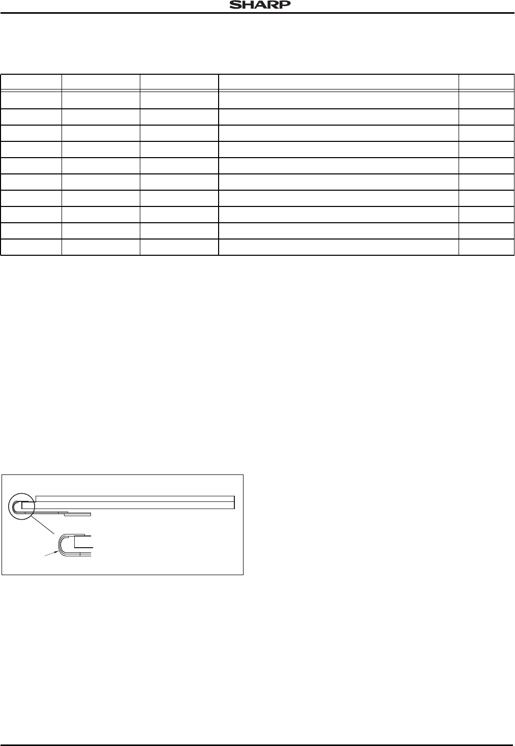
- Connector Specifications 3
- Absolute Maximum Ratings 4
- OPTICAL SPECIFICATIONS 4
- Photo-detector Output 5
- LS013B4DN04-18 6
- LS013B4DN04-3 7
- SIGNAL DESCRIPTIONS 8
- SCS, SI, SCLK Signal 9
- EXTCOMIN Signal 9
- DISP Signal 9
- LS013B4DN04-4 9
- PROGRAMMING 10
- Data Addressing and Positions 10
- Dynamic Mode 10
- LS013B4DN04-5 11
- Static Mode 12
- VCOM Inversion 13
- LCD Modules LS013B4DN04 14
- 14 Application Note 14
- LS013B4DN04-19 15
- LM2750-5.0 15
- LS013B4DN04-20 15
- 9312AD00001FA 16
- BACK SIDE 16
- LS013B4DN04-24 17
- RELIABILITY 18
- Environmental Reliability 18
- Physical Reliability 18
- LS013B4DN04 LCD Modules 19
Verwandte Produkte und Handbücher für Mikrowellen Sharp R-501CW
 (24 Seiten)
(82 Seiten)
(25 Seiten)
(32 Seiten)
(24 Seiten)
(24 Seiten)
(24 Seiten)
(82 Seiten)
(25 Seiten)
(32 Seiten)
(24 Seiten)
 (45 Seiten)
 (24 Seiten)
(26 Seiten)
(24 Seiten)
(33 Seiten)
(16 Seiten)
(24 Seiten)
(26 Seiten)
(24 Seiten)
(33 Seiten)
(16 Seiten)


 (32 Seiten)
(22 Seiten)
(21 Seiten)
(28 Seiten)
(32 Seiten)
(32 Seiten)
(22 Seiten)
(21 Seiten)
(28 Seiten)
(32 Seiten)
© 2020, manymanuals.de. Alle Rechte vorbehalten. | 0.039 s |
 Manymanuals.com
 Manymanuals.de
 Manymanuals.fr
 Manymanuals.it
 Manymanuals.pl
 Manymanuals.cz
 Manymanuals.es
 Manymanuals-pt.com
Kommentare zu diesen Handbüchern