Sharp CD-M4000 Betriebsanweisung Seite 88
- Seite / 204
- Inhaltsverzeichnis
- FEHLERBEHEBUNG
- LESEZEICHEN


- M4000 Insulation Analyzer 1
- User Guide 1
- Structure of this Manual 3
- ENTER. Or, press 4
- 3. Running M4000 Tests 6
- Appendix B. Warranty 9
- Appendix C. Error Messages 9
- Appendix D. Part Numbers 10
- 1. Introduction 11
- M4000 Components 12
- Front Panel 14
- M4200c Controller 15
- Third-Party Controller 17
- M4000 Software 17
- External Reference 18
- M4300 Transport 18
- Storage and Moving Mode 20
- Testing Mode 23
- When Finished Testing 25
- M4000 PC Cable 26
- Shipping Instructions 28
- Safety Considerations 29
- Clearances 30
- Grounding 31
- Personnel Safety 31
- M4000 Connections 32
- M4000 Operation 33
- M4000 Safety Features 33
- Safety Precautions 35
- Instrument 37
- Transformers 37
- Remember: SAFETY 38
- Safety Summary 38
- 2. M4000 Software 39
- Optimization 43
- Time/Date Format 44
- What’s New 44
- The M4000 Program 45
- Menu Bar 46
- Clipboard Test Mode 47
- Icon Description 48
- Menu Items 49
- Temperature Correction 50
- Configuration 51
- Clipboard Configuration 52
- DTA Field Configuration 54
- Instrument Configuration 56
- Advanced Configuration 57
- Using Help 59
- Printer Setup 60
- Printing 60
- Administrative Information 62
- Test Conditions 63
- Test Results Information 64
- Column Description 65
- Raising Test Voltage 67
- Test Results 68
- Clearing Test Results 70
- Saving Test Results 71
- Graphing Test Results 71
- Running A UST Test 72
- Running a GST-Guard Test 74
- DTA Mode 77
- DTA Tests 77
- DTA Data Manager 78
- Preparing for a DTA Test 79
- Starting a DTA Test 79
- 72A-1230 Rev. F 3-23 83
- Figure 3.15 End of DTA Test 83
- DTA Icons and Function Keys 84
- Using A Resonator 85
- OTE Recommended for M2H only 88
- Quick Checks 91
- Troubleshooting Resources 92
- Isolating Trouble 93
- Preventive 95
- Maintenance 95
- Section Purpose Page 96
- Reference 96
- Overview of M4100 97
- 4-8 72A-1230 Rev. F 98
- Avoiding Problems 100
- Troubleshooting from Symptoms 102
- Symptom Suggested Action 103
- Running Diagnostics 111
- System Status 113
- Guard Status 114
- Disabled 114
- Main Reference 114
- Status Disabled 114
- Field Reference 115
- Factory Status 115
- Calibration Verification 116
- Field Recalibration 121
- Subsystem Diagnostics 124
- 72A-1230 Rev. F 4-37 127
- July 22, 2005 127
- M4100 Component List 128
- Thermal Profile 129
- Communications Loopback Test 130
- Running Other Tests 132
- DC Insulation 133
- Resistance 133
- Voltage Verification 134
- Accessing M4100 Components 136
- 72A-1230 Rev. F 4-47 137
- Removing the Card Cage Cover 138
- M4100 Internal Checks 140
- Low-Voltage Power Checkout 141
- LVPS Fuses 142
- W8/W9/W11 Cable Checkout 143
- Orange Cable Checkout 144
- Transformer Checks 144
- W46 Cable Checkout 145
- Replacing M4100 Components 146
- Returning Replaced Components 147
- Ground Nuts 151
- Captive Screws 153
- Side Screws 154
- Top Fan Screws 154
- Guard Mode Switch Board 156
- W8 Connector 156
- W11 Connector 156
- W9 Connector 156
- Replacing the Timing Board 158
- Replacing the DSP/CPU Board 160
- Replacing the Safety Board 162
- Front Screws 164
- Perimeter Screws and Washers 164
- Replacing the Guard Board 166
- Secure Screws 173
- Replacing the Transformer 175
- Whiz Nut 177
- Replacing the HV Pothead 181
- Ground Screw 182
- Replacing the Fan Filter 183
- Replacing the Fan 184
- 72A-1230 Rev. F 4-95 185
- 4-96 72A-1230 Rev. F 186
- Accessory Bag 188
- No. Number Description Qty 189
- Documentation Bag 190
- Appendix B. Warranty 191
- Software Limited Warranty 192
- Limitations of Remedies 192
- B-4 72A-1230 Rev. F 194
- Appendix C. Error Messages 195
- Error # Description of Error 196
- M4000 Communications Errors 197
- C-6 72A-1230 Rev. F 200
- Appendix D. Part Numbers 201
- D-2 72A-1230 Rev. F 202
Verwandte Produkte und Handbücher für Messen, Testen & Steuern Sharp CD-M4000
Tripp Lite PDUMV15NET manuali
Manuali dei proprietari e guide per l'utente per Multiprese Tripp Lite PDUMV15NET.
We fornisce 1 manuali pdf Tripp Lite PDUMV15NET per scaricare gratuitamente in base al tipo di documento: Manuale Utente
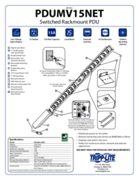
Tripp lite PDUMV15NET Manuale Utente (2 pagine)
Marchio: Tripp-lite | Categoria: Power distribution units (PDUs) | Dimensione: 0.63 MB |

Indice
Più prodotti e manuali per Multiprese Tripp Lite
| Modelli | Tipo di Documento |
|---|---|
| PDUMH20NET2 |
Manuale Utente
Tripp Lite PDUMH20NET2 User's Manual,
4 pagine
|
| PDUMH20HVNET |
Manuale Utente
Tripp Lite PDUMH20HVNET User's Manual,
11 pagine
|
| PDUMH15ATNET |
Manuale Utente
  Tripp Lite PDUMH15ATNET User's Manual,
36 pagine |
| PDU Power Strips |
Manuale Utente
Tripp Lite PDU Power Strips User's Manual,
3 pagine
|
| OMNI1500XLNAFTA |
Manuale Utente
Tripp Lite OMNI1500XLNAFTA User's Manual,
5 pagine
|
| PDUNV |
Manuale Utente
Tripp Lite PDUNV User's Manual,
2 pagine
|
| 200904140 |
Manuale Utente
Tripp Lite 200904140 User's Manual [en] ,
9 pagine
|
| PDUMH15AT |
Manuale Utente
Tripp Lite PDUMH15AT User's Manual,
28 pagine
|
| PS-415-HG-OEM |
Manuale Utente
Tripp Lite PS-415-HG-OEM User's Manual,
2 pagine
|
| TRIPP.LITE PDUMV40 |
Manuale Utente
Tripp Lite TRIPP.LITE PDUMV40 User's Manual,
12 pagine
|
© 2020, manymanuals.de. Alle Rechte vorbehalten. | 0.024 s |
 Manymanuals.com
 Manymanuals.de
 Manymanuals.fr
 Manymanuals.it
 Manymanuals.pl
 Manymanuals.cz
 Manymanuals.es
 Manymanuals-pt.com
Kommentare zu diesen Handbüchern